11. Calibrators
INSTRUMENT REPAIRS & MODIFICATIONS (IN ALPHANUMERIC ORDER)
# Action Status Problem Manufacturer Model Function
1 Repair Ongoing No 2ns Balantine 6130A Timebase calibrator
2 Repair Fixed No o/p General Resistance DAS-45 Precision ±10V Source #1
3 Repair Ongoing Erratic o/p General Resistance DAS-45 Precision ±10V Source #2
4 Repair Ongoing Erratic o/p General Resistance DAS-56A Precision ±10V & ±50mA Source
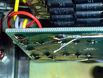
5 Repair Ongoing Corrosion Time Electronics 2003S dc Voltage Calibrator 0.02% #1
6 Repair Ongoing Corrosion Time Electronics 2003S dc Voltage Calibrator 0.02% #3
7 Repair Fixed No output/IEC Time Electronics 9822 Multi-Calibrator 30ppm
1. Balantine 6130A Time Mark Generator
This produces 5s to 100ns pulses & 50ns/10ns/5ns/2ns sinewave, similar in functionality to the Tek 2901: https://w140.com/tekwiki/wiki/2901
https://www.radiomuseum.org/r/ballantine_time_mark_generator_6130a_101_anusm_441.html
https://bama.edebris.com/download/ballantine/6130A-time-mark-generator/6130A%20Schematics.pdf
2. General Resistance Dial-A-Source DAS-45 #1 (2015)
a) Initally worked for a few weeks then the output failed.
Fixed by replacing the 2N2905 PNP output transistor and adding some Arctic Silver TIM (Thermal Insulating Material) aka paste between it and its heatsink.


3. General Resistance Dial-A-Source DAS-45 #2
a) This has an intermittent fault; the output is either correct or far too high with HF ripple superimposed, rather like op amp feedback incorrectly compensated, but cursory investigation turned up nothing obvious.
It may be worth re-examining the voltage reservoir cap ESR:
https://theloopytech.wordpress.com/2015/10/17/misbehaving-frequency-counter-racal-dana-1998/
4. General Resistance Dial-A-Source DAS-56A CC 50mA & CV ±1µV to ±10V, 0.015% 5ppm (2020)
This was expensive, bought as brand new old stock, but has never worked properly. The output is erratic, sometimes it displays the selected value to 5 digits, other times it's wildly wrong. Flicking the polarity switch sometimes cures it, as does power cycling, but neither works all the time and there is nothing obvious to suggest the failure mode.
I've had it fully apart once in an attempt to convert it from US 110Vac to UK 230Vac mains operation but had to abandon this due to poor insulation practices on the mains transformer hidden in a bare metal shielding box.
Other nice little gotchas are: uninsulated wires soldered to feedthrough bulkhead capacitors emerging with live mains on them from the inlet filter; bare mains on the front panel mains toggle and neon power indicator, and an uninsulated phenolic solder tag strip CHECK ORIGIN OF WIRES screwed to the base of the bare metal box (the screw isn't secured and can be undone from the outside).
a) Bare mains is all over the inside: PHOTOS 300 to 310 [renumber later]


Believe it or not, the ultra flexible thin grey wires with super thin insulation (see photo below right) carry not only secondary voltages, but mains to the primary. The insulation is so thin I would not trust it for US 120Vac ±5% = 126Vac max, let alone UK 230Vac -6% +10% = 253Vac max (peak voltage 253Vrms x √2 = 357V). Bizarrely they used thicker insulated wires (RD/YW/OE) only for the outputs of the rectifiers:


I also found a 15mm long bare wire hanging off the KVD assembly, and the handled metal lid scrapes the pcb at the back when you remove or re-attach it.
Poor soldering is not the same as untidy looking circuitry, often beneficial to noise reduction. For good examples of this skilful art, look at Jim Williams' AN-47 Appendix F [J1].
I have found a general rule of thumb is, if the company isn't that well known and it looks professional on the outside, it probably isn't inside. The performance-lauded classic QUAD 33 from famous British manufacturer QUAD Electroacoustics managed to achieve both: placing loose rows of pushbuttons with so much vertical play all adjacent lettering was misaligned in its amateurishly futuristic simplistic orange and grey box and looking inside, I found components thrown into their positions without a care.
Below, instances of poor soldering on mains; generally the soldering to switches is poor everywhere.


BEFORE I START FAULT-FINDING I WILL FIRST INSULATE ALL BARE MAINS CONNECTIONS.
b) Output set to 1.00000V spanned +12V to -2.7V over 8 hours: PHOTOS 330 to 340 [renumber later]


Below left, a small analogue pcb is plugged into the large power supply board at the rear of the unit.

5. Time Electronics 2003S ±9.9999Vdc Calibrator #1 0.02% (2024)
Very old (pot dated 1977?), batteries heavily corroded & pcb also very tarnished & filthy.
A few screws & washers missing.
Newer? version fixed here (excellent video teardown & repair):
https://www.ianjohnston.com/index.php/videos/144-video-blog-113-2003S
It never occurred to me to use an ultrasonic cleaner on the pcb assy until I saw this.
He also offers an excellent 20-bit DAC-based 0-10Vdc cal for £325 (in 2023 very good value but a bit too expensive for me). Hopefully this much cheaper 2003S can be repaired. Not as good a spec, but enough for my needs.


7. Time Electronics 2003S ±9.9999Vdc Calibrator #3 0.02%
Not as old as the last one, batteries and 78M18 IC have some corrosion.
The ultrasonic cleaner is now my first port of call with these.


8. Time Electronics 9822 Multi-Calibrator 30ppm (2022)
a) Erratic controls turned out to be the Motorola 68A21P again:
June 2024:
b) Fired it up and after a few minutes I heard a 'Pfffft' noise accompanied by a nasty burning smell.
Opening the case, the smell seemed most apparent in the transformer plugin. Removing this revealed potting residue on the IEC inlet filter, the exact same thing that happened to the HP4952A Protocol Analyser see [General Instruments], despite the lab mains now reduced to 230Vac from the raw 250Vac, see Foreword in [Mains Variacs & Regulators].
Marked on the IEC is Schaffner FN372-4/--, the 4 designating 4 amps. The fuses are 20mm types so the full part number should be FN372-4/21 where the 2 designates inclusion of a mains selector, and the 1 indicates the fuse is an EU 20mm type vs USA 6.25mm. Digikey sells them in the Uk for £18 + £12 post.
It seems to still function with the buggered IEC filter (I assume a capacitor let go) but the 9822 cost £500 and I don't want to press my luck so I'll get a replacement IEC before I do anything else.
I'll add having bought a 9822 service manual, I have to say Time Electronics' schematic is garbage. Really badly drawn, incredibly hard to relate to the instrument with missing components and connections. It looks incredibly amateurish (as does the pcb inside their 2003S) but I will assume it's this crap because they wanted to prevent competitors from stealing their design. IMO it should be sufficient simply to omit the detail of the potted reference (which they do) so really there's no excuse.
I thought it had another fault when I tried to produce a 1kHz HV pulse and nothing came out but then discovered HV only works with sine waves.


ORIGINAL BATTERY:
Spec found on battery label [LIBS6 P.167]:
Varta Type 400DK, Average 1.22V per cell
Charge at 1.35V to 1.50V per cell, 40mA for 14 hours
Do not discharge below 1.1V per cell.
With the extra cell on the pcb added, 12.2+1.2V = 13.4V total
6. Time Electronics 2003S ±9.9999Vdc Calibrator #2 0.02%
text
New text box
µ Ω ± ° ⌠ ⌡ ∫ │ ─ √ φ θ Θ ∂ δ ζ ξ ς λ ψ ω τ µ Ω ∆ Δ ∑ ∏ π Ξ ○ ≠ ³ ² ±