6. Spectral Gating
My two biggest concerns for the LHC Project are the slow speed of the PCM-401, and the possibility of laser reflections and Bremsstrahlung radiation damaging its PDA image intensifier.
Whilst I was investigating enhancements to counter the speed issue, in the background I mulled over the second problem. At first I considered a dichroic bandpass mirror could pass just 200nm-1000nm to the spectrometer until I realised the radiation is a continuum covering a wide spectral band from X-ray to IR and I remembered I wanted to experiment with multiple laser wavelengths hitting the target; 532nm and 266nm fall within that range.
It seemed the only solution was a mechanical shutter, one that would only admit light to the spectrometer once the radiation had passed. I returned to the timing diagram to estimate the duration.
The Kigre diagram [O6] (below left) suggests Bremsstrahlung continues up to 2µs, and thereafter atomic spectra to 100µs. I found a similar diagram embedded in a slideshow [L8] (below right) from Wayne State University, IL., derived from page 24 of the Handbook of Laser-Induced Breakdown Spectroscopy [L2]:

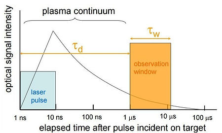
LONGER WAVELENGTHS EXTEND EMISSION TIME
New information from the diagram on the right, is that the intensity of the spectral signature understandably decreases exponentially over the 100µs period depicted in the Kigre diagram. I had read elsewhere that atomic spectra are still visible into the milliseconds, but these levels would likely be so diminished as to be indiscernible to most LIBS detectors.
Finding this diagram led me to its original source [L2] and its accompanying text:
'The timescales shown in Figure 2.1 are appropriate for a plasma initiated in air at 1 atm by a
5 to 10ns 1064nm laser pulse from a Nd:YAG laser. For much longer (e.g. CO2 laser) or much shorter pulses (e.g. pico- or femtosecond lasers) the timescale will expand or contract accordingly.
As ambient pressure decreases, the plasma lifetime decreases because there is less trapping and recycling of the absorbed energy in the plasma volume.'
The first sentence suggests CO2 might be a better laser for the PCM401, and the latter confirms a pressurised target is better than one in a vacuum, (I continue to find papers suggesting a vacuum has advantages).
More important, the first sentence suggests the longer the laser wavelength, the longer the atomic signature. Could this also mean DUV would result in a signature so short I could not detect it, effectively cancelling the advantage of the better quality signal afforded by DUV?
What if I had both a DUV (193nm) and a CO2 (10.64µm) laser hitting the target?
I found confirmation of shorter wavelengths affecting the spectral timeline in [L9], Laser-Induced Breakdown Spectroscopy, Page 173: 'It has been found that the plasma and continuum emission decreases significantly with lower pulse energies and thus one can obtain reasonable performance without using temporal gating. The term µLIBS has also been used in the context of applications with ablation spots of micron scale size [5,6]. In most cases, the definitions based on µJ energy and micron resolution spot sizes are equivalent.'
I have not found any relative measurements of the intensity of Bremsstrahlung vs. the intensity of atomic spectra. It seemed I would have to measure this and the effect of laser wavelength on atomic spectral decay myself, and bought some sacrificial low cost PMTs.
2026 Google AI:
Bremsstrahlung radiation is emitted instantly, within picoseconds to a few nanoseconds of the laser pulse striking the target. [1, 2, 3]
It begins the exact moment the leading edge of the laser pulse delivers enough energy to ionize the surface material and free the first wave of electrons. [1, 2]
The timeline of Bremsstrahlung radiation in a standard nanosecond Laser-Induced Breakdown Spectroscopy (LIBS) setup unfolds through the following phases:
Timeline of the Radiation
0 to 10 ps (The Impact): The laser hits.
The electric field of the laser strips electrons away from their parent atoms. [1, 2, 3]
10ps to 10s (Bremsstrahlung Peak): As long as the laser pulse is actively firing (typically a 3–10 ns pulse), it rapidly heats these newly freed electrons, accelerating them to extreme speeds. These high-speed electrons violently decelerate as they swerve past positive ions. This braking action releases a blinding, continuous white light. [1, 2, 3, 4, 5]
10 to 100ns (The Cool Down): The laser pulse ends. The plasma plume expands rapidly into the surrounding air, beginning to cool down. The electrons slow down, causing the Bremsstrahlung radiation to rapidly decay
0 - 100ns: Bremsstrahlung Dominates ──► (Blinding white noise spectrum)
10 ns - 2 µs: Atomic Lines Emerge ──► (Useful elemental data collected)
The atomic spectra intensity typically peaks between 200ns 1µs after the initial Bremsstrahlung radiation begins to clear.
MECHANICAL SHUTTER
First I needed to check if a mechanical solution could work. To add a little safety margin, I would like the shutter to admit light to the MCP at least 4µs after the laser strike, and stay open for 100µs. The laser firing signal would also have to be derived from the shutter to keep the two synchronised and the signal would ideally be routed using FO. [O61] Bore diameters for a standard SMA0905 FO termination are 128µm to 1580µm (0.128mm to 1.58mm). My Stellarnet spectrometer FOs are 600µm and 1000µm [I NEED TO MEASURE PCM FO BORE DIA]. The shutter would need a wide enough aperture to admit this.
My first thought was a rotary shutter driven by an electromagnetic solenoid but I found they typically switch in 3ms. That left a rotating disc as the most affordable option. Next I had to work out how fast it had to go and how big a disc I needed to obtain a 100µs - 4µs = 96µs wide gap for the light to pass through. I reasoned the laser could be fired using a small hole somewhere else on the disc for an optical trigger beam to be interrupted before the MCP gap appeared.
The next idea was to attach a disc to a 120mm computer fan, and typically these run up to 3,000rpm. A 120mm fan ~ 4.72", so I considered a 4.5" disc with a circular slot 2" from the centre (4" pcd):
The circumference of a circle is 2πr, a slot 2" from the centre = 2 * π * 2" ~ 12.57".
3000rpm/60 = 50rps. In one second at 3000rpm I would get 50 x 12.57" of travel ~ 628.32".
1 second / 628.32" ~ 1.59ms per inch.
1.59ms/96µs ~ 1/16.58" ~ 0.0603" per second x 25.4 ~ 1.53mm long slot.
If the motor was 6000rpm then it would be 3.06mm.
If the disc was 8" it would be 6.13mm, and 6" would be a reasonable compromise at ~ 4.6mm.
The idea seemed feasible.
I bought a 6000rpm fan and tried it on the bench: at full speed it howled and tried to vibrate itself off the bench and even driven by a precision digital PSU, the speed varied considerably. I realised the impracticality of going this route and that I would either have to build a precision feedback control loop using its pin 3 tacho output (which would probably be little better as it is only a fan after all), or buy a good quality synchronous motor, or find an instrument that did it for me. Remembering the mess I got into at university with analogue motor feedback control loops, I opted for the latter.
These instruments are called optical choppers (http://en.wikipedia.org/wiki/Optical_chopper) but on eBay, more often than not the controller appears without the chopper and most models are very old. I settled on a newer UK-manufacturer Scitec 300CD http://www.scitec.uk.com/optical_chopper/300cd (datasheet here: [I17]). This also appears to be the OEM version of Edmund Optics 55-783 chopper: https://www.edmundoptics.com/p/optical-chopper-115-vac/12580/# still a current model but cheap on eBay.
It only has small 102mm (4") diameter discs, but I reckoned I could retrofit a larger disc.
Once I found out the motor was a Maxon 2326.945-12.111-100 I bought a controller for $22, thinking I'd buy the motor when one came up and build my own custom chopper. I had just found an equivalent
Maxon 2326.945-12.111-050 on eBay China for $35 when by sheer luck a complete 300CD with the motor and a large selection of 102mm discs appeared in the UK at $25 with no other bidders, and it even cam with a free magnetic optic clamp. It's capable of producing pulses up to 20kHz with a 200 slot wheel but my fastest only has 30 slots.
At max speed with 30 slots on a 102mm disc I measured 3.289kHz max (304µs) = 6578 rpm. However for the sake of argument, assuming 6600rpm max = 110Hz = 9.091ms/30 = 151.5µs per slot. A 102mm disc with 200 slots at 6600rpm would produce 22kHz (45.45µs) disc would be 22.73µs per slot.
A 30 slot 102mm (2") diameter disc has a maximum slot (light admittance) width of:
disc circumference (=2πr)/60 = (2 x π x 25mm)/60 = 5.34mm across 151.5µs @ 6600rpm.
A 200 slot 200mm (4") diameter disc has a maximum slot (light admittance) width of:
disc circumference (=2πr)/400 = (2 x π x 100mm)/400 = 1.57mm across 22.73µs @ 6600rpm.
A 200 slot 400mm (8") diameter disc would have a maximum slot (light admittance) width of:
disc circumference (=2πr)/400 = (2 x π x 200mm)/400 = 3.14mm across 22.73µs @ 6600rpm.
As noted previously, a bigger disc is needed to achieve a useable slot length at 6600 rpm.
I would not need 200 slots, instead just 3 apertures for trigger, gate and aux timing, although there may be a structural advantage to a drilled disc (less weight, possibly greater strength) and holes could be made towards the axis. The Scitec discs are made of brass. The largest eBay UK discs are 108mm diameter but unmachined. Unless I can find large discs from a different chopper, I will have to employ a machine shop to ensure a perfect central hole, lightening holes, and a precision circumference for balance at high rpm.


BREMSSTRAHLUNG RADIATION INTENSITY MAY NOT BE AN ISSUE
Finally in 2022 I chanced upon a link [L46] to a YouTube video describing the first true DIY line-based LIBS system I had seen: https://www.youtube.com/watch?v=D1HU-7zP9xo Within this video a twin graph is depicted, top: Bremsstrahlung continuum radiation intensity, bottom: atomic spectral line intensity.
A quick search revealed it is Figure 1.4 on Page 5 of Handbook of Laser-Induced Breakdown Spectroscopy, Cramers & Radziemski, 2006. However the font looks ancient and there is no explanation for the annotated spectral graph peaks, so it must have originated in an earlier press such as those listed on the preceding page: Laser Microspectral Analysis: A Review of Principles and Applications, R.S.Adrain & J.Watson, J.Phys, D:Appl.Phys. 1984; or other LIBS Handbook revisions from Cramers & Radziemski, viz: 1987; 1989; 1994 and 1997. Unfortunately I have no access to these publications.
The graphs have identical horizontal scales from 385nm to 410nm; the differing vertical axes are defined as arbitrary but appear to represent the same units. Spectral peaks are annotated but the meaning is lost without the original text.
The Bremsstrahlung continuum intensity varies between 5000 and 6500 arbitrary units.
The atomic line intensity varies between 5000 and 15000 arbitrary units.
In the absence of an explanation, I am tempted to infer the units of the vertical axes are identical.
If this is indeed the case then Bremsstrahlung radiation intensity levels are nothing to worry about.
The mechanical shutter however is still required to protect the MCP from the laser and its reflections, and to ensure the detector is gated for atomic spectral emissions only.
MECHANICAL SHUTTERS HAVE BEEN USED FOR LIBS
[L4] Approach to Detection in Laser-Induced Breakdown spectroscopy, 2007, compares a mechanical chopper wheel delayed CCD with a MCP gated iCCD and a 400mm, Aryelle 400 spectrometer also mentioned in [L5].
'The non-intensified CCD system was timed through the electronics of a chopper wheel, which provided the trigger (t = 0s) signal for the flash lamp, the Q-switch, and the detector. The chopper provides a minimal rise time of 200ns and has a 100ns jitter with respect to the laser pulse.'
This is the closest to what I have in mind for my own system.
The question now is how fast did they run the chopper? Better, which one did they use?
[L5] Analysis & Identification of Solid Materials by LIBS: A Comparative Study with Four Spectrometers,
2012. The 400mm Aryelle spectrometer differs from the others by using a mechanical shutter to provide a 10µs delay: 'The CCD is used in combination with a mechanical chopper, which blocks the early continuum radiation from the plasma'.
This statement was one of the main reasons I initially assumed Bremsstrahlung radiation is an optical hazard. My new assumption from the graphs in [L46] that Bremsstrahlung may be harmless, suggests 'blocks the early continuum radiation' merely ensured only spectral lines reached the detector.
The spectrometer with the shutter is an Aryelle 400 spectrometer made by LTB Lasertechnik, Berlin:
http://www.ltb-berlin.de/en/products/spectrometers/aryelle-400/
Their dedicated LIBS page also lists the Aryelle 400 as an option, but there's no mention of a chopper:
http://www.ltb-berlin.de/en/products/analyzers/libslab/
This paper implies the chopper is actually part of the spectrometer but it is possible only a standard CCD-based Aryelle 400 was to hand and due to the absence of a gate the authors added the chopper in front of the entrance slit. I'm suspicious it's the exact same spectrometer used in [L4] and I suspect as this is a later paper, they copied the idea from the earlier one.
[L4] Makes further interesting reading: 'In laser-induced plasmas, line emission is superimposed on an intense continuum radiation that dominates plasma spectra during the first hundreds of nanoseconds. To cut off the continuum, a gated detector is necessary that gives an obvious advantage to an ICCD over a CCD. However, if the collection startup time of a CCD is delayed, (e.g., by mechanical chopping), then the SNR for a CCD can become comparable or even higher than that for an ICCD...the high gain of an ICCD ...does not yet guarantee a superior SNR. Photon noise in an ICCD is amplified by the MCP to the same extent as an optical signal. Therefore, the overall higher quantum efficiency of a CCD is able to provide a far better SNR compared to an ICCD.'
This is beginning to suggest I remove the MCP and continue with my chopper idea, but the PCM has a PDA not a CCD. Would any advantage be lost?
This 2012 paper [O35] says PDAs have superior dynamic range to CCDs:
'important advantages of PDAs..scan rates, dynamic range, accuracy and sensitivity. A main advantage is the dynamic range of PDAs of 10^6 compared to CCDs: 10^3 or at best 10^4. In addition, PDA signals can be alternating current coupled with long time constant and background fluorescence can be subtracted with analog circuitry before digitization making it possible to take the full measure of digitization range. (14 bit) and achieve considerably greater accuracy than any other photodetector'
https://www.ahajournals.org/doi/pdf/10.1161/circresaha.112.270033
MOTORISED Q-SWITCH
I have not yet determined whether the same disc could be used to Q-switch a laser but given the difficulty of mechanically achieving a relatively slow shutter delay of 10µs before the detector is enabled, and having noted a specified 8ns pulse from a Q-switch based on a rotating prism [O60] and Sam's laser FAQ mentioning one running at 30,000 rpm, I wonder if the two can be combined. Q-Switch prism motors do tend to be fast (I have seen 36,000 rpm mentioned) and they rarely come up on eBay and when they do they are often knackered; the good one I did find was sadly lost in the post.
There still is some hope: Mil document [O14] describes a 6,000 rpm motor producing a 32ns pulse with a LD: 'Chopper wheels contain 60 slots or apertures, allowing a maximum repetition rate of 6kHz. Two chopper wheels with diameters of approximately 98mm and 109mm were used. The ratio of the opaque area to the transparent area is 1:1. At the maximum motor speed, the linear velocity of the aperture edge near the outer edge of the 98mm diameter wheel is 3.1 x 10^3 cm/sec. Thus approximately 32ns is required for the aperture blade to traverse 1µm. The wheel with the lowest phase error (±0.2°) contained two slots and provided a repetition frequency of 200Hz (2 sandwiched discs running at 6,000 rpm) at the evaluation of the mechanical Q switch.'
However this was for a mW power LD, vs MK580KK power in the MEGA-watts:
'The observed pulse width of average Q-switched power to CW power in the pulsed pumping were measured as a function of the pump power. At 3kHz the ratio is 0.58 for a pump power of 50mW. The free-running power increases The ratio decreased to 0.34 at a pump power of 500mW. The threshold pump power is 31mW with an 0.899-R output coupler. The Q-switched pulse widths were 160ns at the lower pump power, decreasing to 28ns for the 500mW pump.' HE Q-switching may not be viable.
USE A BAND NOT A DISC
Everything suggests a 4" disc at 6600 rpm is not big or fast enough for spectral gating, let alone
Q-switching. The larger the disc, the more unwieldy, and increased speed would probably need a safety enclosure that would also minimise external influences.
An alternative to a disc is an endless lightweight rotating band. The band could be much longer than an equivalent disc, although I am not sure how fast it could go (crude band sanders typical run up to
3450 rpm / 8000 surface feet/minute, so 6000 rpm may be achievable). Large spindles each end would provide a wide space between the outgoing and incoming tape sections, permitting the signals to be gated on either of the directional band strips, further extending their equivalent timing slot length. If the spectrometer FO is directed through a 90 degree mirror it can pass through one band which would provide the longest gap, although this might impact on the material band: it would have to be sturdy enough o support a long hole in it although in reality only a few mm. Alternatively it could pass through both band directions where they align.
2026: Google AI seems to think it can be done using a 4" disk but I'd have to get a machine shop to makethe disc and cut the slots to ±0.01mm.
Text
Text