14. Other Repairs, Modifications and Teardowns
INSTRUMENT REPAIRS & MODIFICATIONS (IN ALPHANUMERIC ORDER)
# Action Status Problem Manufacturer Model Function
1. Repair Fixed Stopped working Hangsun HOC700 Oral Irrigator
1. Hangsun HOC700 Oral Irrigator (water flosser) (2024)
Problem: Stopped working
Xmas 2023, a relation gave us a new Hangsun water flosser she recommended, that we had earlier enquired about. It worked fine for 9 months and then started doing strange things. First it started coming on by itelf in the middle of the night, then it ignored selected speed settings and eventually after about a month, the on/off push button no longer lit its blue LED or started the motor, yet the function select push button below it lit the 3 speed selection LEDs in sequence as usual although they too went off after about 15 seconds.
A search in the 'Net revealed the following repair of an outwardly similar model with a different manufacturer and slightly different pcb, the fault here apparently being down to the chip in the Li-ion battery needing to be reset:
https://www.drive2.ru/b/637944618968687117/

However this could not be our problem as the function select button still did something, albeit useless. The only solution was to open it up (hover over each photo below for its explanation):


Inside I found water drops on the pcb and visible signs of corrosion. We had never immersed it, so this must be down to bad sealing.


The 3.7V 1400mAh Li-ion battery seemed fine and was fully charged, sitting at 4.0V.


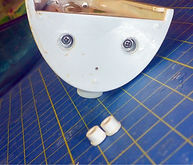
Below, the underside showing the pump outlet and, split open, the motor and battery in the centre.


I removed the pcb, cleaned off the corrosion, left it to dry overnight in a warm airing cupboard and tried it again the next day but it made no difference.


The pcb is also marked Rentech and a quick search revealed they are the OEM, not Hangsun. Rentech had actually paid attention to the possiblity of leaky seals bcause the pcb has a conformal coat, but it wasn't very well applied and there were big gaps. I scraped it off the tops of the ICs and two SOT-23s near the motor take-off in the hope of identifying them.
Below left, the SOIC-16 marked Rentech FS012 is the µC.
Centre, the SOTs are numbered 2300 which identifes them as BM2300 Trench NMOSFETs: 20Vgs, 5.2A/20Apk, 1.5Vgth, Ron 40mΩ. Very nice.
Right, the SO-8 IC near the battery terminals is a TP4056 Li-ion charger IC. Despite the huge amount of corrosion on it initially, it evidently still worked.


I now began tracing the pcb tracks from the uC, identifying port pins for the switches, the motor drive and out of curiosity, the LEDs.
µC pin 5 leads to series resistor R4 1kΩ and pulldown R10 100kΩ on the NMOSFET gates. The MOSFETs are wired in parallel, I assume to halve Ron.
To their right are a couple of big SMD 50mΩ sense resistors which I assume are for current feedback as they connect in parallel to the MOSFET source and into a resistor routed in the direction of the µC.
The top ON/OFF switch S1 goes to µC pin 2 with R19 10kΩ pullup.
The lower FUNCTION SELECT switch S2 goes to µC pin 3 with R20 10kΩ pullup.
µC pin 1 is V+ and pin 16 is 0V.
The LEDs are driven off µC pins 7,12,13 with 100Ω current limiting resistors R15, R7, R6.
I didn't trace any more circuitry, mainly because the tiny SMDs are covered in conformal coat and at that point I still hadn't got around to buying some nice sharp probes, although afterwards this finally prompted me to order some.


Hooking up a 4V PSU and pressing the buttons, NMOSFET drive µC pin 5 was always ~0.4V.
Uncertain if there was a µC O/P fault or a short on it, I pulled out series R4, injected 2V and with a 5V incandescent lamp in place of the motor (you can only get the pcb out by unsoldering it from the motor) and confirmed the NMOSFETS worked.
Examining S1, I got 0.4V nominal until I pressed it when it dropped to 0V. S2 went from 4V to 0V when depressed. There are 2 vias on the pcb tracks leading to S1 and I drilled them both out but it still remained at 0.4V. Unable to debug further I assumed the switch was faulty. Since S1 was now disconnected from its µC pin 1, next I added a 10kΩ pullup and tried pulling it low, but it still didn't work, indicating a problem with µC pin 1 too.
I rarely chuck stuff in the bin but that's what I did next.
The next morning in my bath it occurred to me all I had to do was feed S2 into an inverter to drive the NMOSFETs in place of the µC, and I retrieved the bits from the bin.
I found a 74HC1G02 single NOR gate in a SOT-353 but my first choice 10kΩ was too big; the nearest fit was a 2k1Ω.
I unsoldered the µC using low temperature ChipQik solder and cleaned the pads with braid.


Above right: since V+ came into the µC at pin 1 and S2 came in at pin 3, I soldered it between these pins, adding a pullup 10KΩ SMD between them, a wire to 0V on pin 16 and a wire to a 1kΩ SMD soldered to pin 5 leading to the NMOSFET series R4 I had pulled out and now shorted with a solder blob (poor practice but fine for this: it was hard enough soldering my bigger SMD Rs in place but far more difficult putting the tiny R4 back without disturbing surrounding SMDs).


I checked it worked with the lamp and sprayed on more conformal coating.
I cleaned dirt off all assemblies when I dismantled it. I now removed mould growing inside the water tank, and mould in the water pickup tube with a pipe cleaner: something to watch out for in the future.
I also added grease around the various O-rings; it won't last forever but should improve what was there. I re-attached the pcb to the frame and soldered the motor back in. The nozzle release button is a little fiddly but it's only a matter of pushing it through its recess in the top before re-assembly.
The flosser is now working again, albeit stuck on its full power setting which is a little fierce (I may replace the gate with a regulator) and there are no LEDs on now, but that's 4mA less from the battery.
New text box
µ Ω ± ° ⌠ ⌡ ∫ │ ─ √ φ θ Θ ∂ δ ζ ξ ς λ ψ ω τ µ Ω ∆ Δ ∑ ∏ π Ξ ○ ≠ ³ ² ±