9. Project Lasers
An excellent description of the basic properties of lasers, from electrons to NLOs and beyond, is given in Chapter 1 of [O59]: user manual for Quanta Ray / Spectra Physics GCR series of lasers.
The project explores multiple lasers:
SEMICONDUCTOR
# Manf Model Type Class Col λ Mode Dia long Energy Power Purpose/Status
1 Chinese - Diode II Red 632.0nm CW 1.0mm - - 1mW Alignment
2 Axcel CMA64 Diode IV NIR 1064.0nm CW 100µm - - 2W Optics setup
3 Synergy - Diode IIIa VIS 532.0nm CW - - - 200mW Optics setup
4 LsrExp LCS-DTL-374QT LD IV UV 355.0nm Q-swt 1.0mm - 20µJ 420mW DEAD
YAG ASSEMBLIES
5 Kigre MK367 Nd:YAG IV NIR 1064.0nm Q-swt 3.0mm 100mm 25mJ 6MW @ 4ns Prototype
6 Sunrise M580KK Nd:YAG IV NIR 1064.0nm Q-swt 5.0mm 1J est. 140MW @ 8ns LHC
7 Sunrise unknown Ho:YAG IIIa SWIR 2100.0nm CW 4.0mm 260mW Experimental
YAG BRICKS
8 DIY Lumenis Nd:YAG IV NIR 1064.0nm CW 4.0mm 97mm Experimental
9 DIY Lumenis Er:YAG IV SWIR 2940.0nm CW 4.0mm 97mm Experimental
RODS
10 DIY - Ruby IV Red 694.3nm Q-swt 6.0mm 102mm J est. Experimental
10 DIY - Ruby IV Red 694.3nm Q-swt 8.0mm 75mm J est. Experimental
10 DIY - Ruby IV Red 694.3nm Q-swt 8.0mm 120mm J est. Experimental
11 DIY - Ti:Sapphire IV Red 700.0nmT Q-swt 8.5mm10.5mm J est. LHC
12 DIY - Alexandrite IV Red 755.0nmT Q-swt 5.0mm 117mm 1J est. Experimental
13 DIY - Nd:Phosphate IV NIR 1053.0nm Q-swt 8.0mm 90mm J est. Experimental
13 DIY - Nd:Phosphate IV NIR 1053.0nm Q-swt 10.0mm 218mm J est. Experimental
14 DIY - Nd:YAG IV NIR 1064.0nm Q-swt J est. Experimental
15 DIY - TmHoCr:YAG IV SWIR 2081.0nm Q-swt 4.0mm 89mm J est. Experimental
GAS
16 LsrPhys 50S Argon IIIa Blue 488.0nm CW 0.7mm - 5-50mW LHC
17 LsrPhys 500M Argon IIIa Multiline CW 0.7mm - 30-300mW DEAD
18 Rofin 6329A HeNe II Red 632.9nm CW 1.0mm - 1mW DEAD
18 MG 05-LHR-111 HeNe II Red 632.9 CW 0.6mm - 2mW Optics setup
19 DIY - TEA CO2 IV LWIR 10640nm CW TBD 100W Experimental
Key:
T - Tuned
Class - [O2] Class I <1mW, Class II 1-5mW, Class IIIa 5-500mW, Class IV >500mW
CW - Continuous Wave
Q-swt - Q-switched
LHC - Main project
Axcel - Axcel Photonics
LsrExp - Laser Export
LsrPhys - Laser Physics
More information
The following webpage is an excellent primer on lasers:
https://www.rp-photonics.com/lasers.html
Chapter 5, pages 183,184 of 'The electro-optics handbook 2nd Edition, 2000' by R.Waynant, M.Ediger [O29] features tables showing the most likely excitation sources for several laser media, including:
Alexandrite 700nm - 820nm flash lamp
CTH:YAG 2081nm flash lamp
Nd:YAG 1064nm flash lamp, LD
Nd:YLF 1047nm flash lamp, LD
Ti:Sappire 660nm -1200nm flash lamp + Nd:YAG -> 2HG, Argon laser
SEMICONDUCTOR
1 Chinese laser diode, generic cheap LD module, cost about $5.
This will be used as an optics alignment laser, shone through the laser rods.
Add 20801...JPG photo of LD
2 Axcel Photonics 1064nm DPSS
Bought 4 on eBay from Chinese seller laserdirect who said they were new from Laser Components USA, but they are just a distributor, although the seller seems genuine. The Axcel Photonics CM-A64-2000-150 (C-Mount 1064nm ±5nm 2W 100µm aperture) on their website was the closest match I could find and it seems likely they are this or a very similar part. The seller provided power curves and confirmed VF 1.5V to 2.0V. The lasing threshold of the Axcel parts is around 1.1 to 1.2V. I bought these to experiment with 1064nm optics and test the viability of beam attenuation before the liquid cooled flash lamp pumped Nd:YAG is operational.
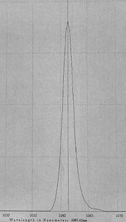
I built my own custom driver using a Wavelength Electronics WLD3343 hybrid LD driver chip [D16], a heatsink and fan coupled to two TECs, and a NTC thermistor, driven by a simple LM339 window comparator feedback loop to control the temperature with a trim pot. The LD worked for a short while then failed, but not before I had verified it lased at 1061nm, see below. I'm not sure if it failed due to a localised hotspot, or simply ESD. Despite taking precautions at the time, I'm inclined to think the latter and I have since upgraded my lab's ESD facilities (the literally shocking nylon carpet now has a grounded ESD mat over it) and invested in Lasorbs [D4] to protect the remaining LDs for future experiments, for which I later acquired dedicated TEC [I18] and laser [I19] driver instruments. At $100 a LD, I'd rather not blow any more.
Below left, spec sheet for the 2W 1064nm CW LDs Below right, TEC comparator pcb

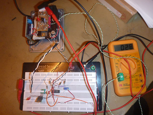


Above left, testing the prototype TEC comparator circuit (LD is OFF!) using a thermocouple-capable DMM before building it on the blue pcb (top right photo) located on top of the small fan that cools the heatsink fins. The comparator feedback loop regulates power to the two Marlow RC6-4 TECs [D17] (see photo below left) connected in parallel to the main +8V supply. The thermistor (twisted black & white wires) is located on one corner of the LD heatsink that is secured to the top (cool side) of the TECs.
In the above right photo the 1064nm LD can be seen to the left and like the metal top surface of the WLD3343 driver chip to its right, is bolted to the top of the heatsink.
Below left: the white gunge-looking material around the female crimp contact mated with the LD lead, is in fact solid polymorph smart plastic material [G7], that I moulded into shape after melting it in water heated to 62°C.
The pins on the bottom (red/green) side of the WLD3343 LD driver plug into a DIL socket on the pcb above it that also has the assembly power switch and its LED. This pcb contains the minimal ancillary components for the WLD3343 driver, such as its large 1Ω 5W sense resistor (top right: cermet, white), and white adjustment trimpots on the pcn underside below the LED, middle of the photo below, left.
The large vertical pcb on the left side is an Astec 5V 2A dc converter for the logic and laser driver.
Below far right: my Stellarnet Comet SR spectrometer confirmed LD lasing at 1061.45nm at 25°C.


Below left: The small pcb with two electrolytic cans each side of a blue trimpot, is an eBay China +24V step-up converter to drive the fan which was in my parts box. Centre, a strip of fluorescent paper helps reveal the 1061nm beam to my Panasonic FT4 camera. Finally, the diecast aluminium box housing the entire assembly.
ADD CCT IN PLACE OF 20809


3 Synergy S500 DPSS
Type: LD module
Pump: 808nm LD
Dimensions: Total 160mmx120x50mm
Extras: Controller & PSU
Mode: CW
Wavelength: 532nm via NLOs
output power: 200mW (2W LD fitted)
Polarity: unknown
Bought non-working for £45. The label says 500mW max. Replaced the original C-mount LD with a $17 1W Chinese one. Without altering the electronics max power is 200mW which is fine = extended life.
4 Other lasers bought for experimentation
Manufacturer: Laser Export, Russia
Model: LCS-DTL-374QT
Type: YV04 810nm > 1064nm + 532nm > 355nm
Mode: Q-switched
Wavelength: 355nm (810nm, 532nm, 1064nm)
Output power: 355nm 30µJ 10ns / 355nm avg 50mW / 810nm, 532nm, 1064nm avg 420mW
Polarity: unknown
This arrived in poor condition but remarkably still worked to a degree, producing a small amount of 808nm and insignificant 1064nm. My initial repair restored low intensity 532nm and very low 355nm:[Repairs: LCS-DTL-374QT 355nm laser] The next step is to replace the worn out fundamental source.
YAG ASSEMBLIES
5 Kigre MK367 Nd:YAG
Type: Nd:YAG
Pump: Flash lamp
Dimensions: Total 98mm x 4mm dia
Mode: Passive Q-switch
Wavelength: 1064nm
Output energy: 25mJ
Output power: 6MW @ 4ns
Max frequency: 0.3Hz
Polarity: S polarised
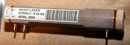
This is the prototype LIBS laser.
Meredith Nd:YAG with FO focus lens
6 Sunrise? M580KK Nd:YAG
Type Nd:YAG
Pump: Flash lamp
Dimensions: Rod 78mm x 5mm dia
Mode: CW
Wavelength: 1064nm
Output energy: 1J (Q-swt Est.)
Output power: 140MW @ 8ns (Est.)
Max frequency: 20Hz (Est.)
Polarity: TBD


M580KK Nd:YAG with MK367 at front
Bought on eBay from a Russian sounding seller based in the USA who provided photographs of it firing. No manufacturer name save for a label Kigre M580KK. The seller said it had come from a German medical company. Kigre confirmed: 'The pump chamber is model FC-M580KK and was not shipped with a laser rod or flash lamp so we don't have any energy specs. The resonator bench isn't ours. The recommended flash lamp was our K300. The filter tube is Kigre's KK-1 glass'. A later auction for a laser assembly made for Sunrise Lasers looked surprisingly similar and Alma GmbH makes lasers for them, so I am assuming this is an Alma laser. The flash lamp manufacturer and model is unknown. The seller got it running off 1750V using a Kaiser LS1000 power supply he had modified, but I think this voltage is too high.
I bought a very similar one from Meredith Instruments eBay as a spare, but I have no idea if it works. This one seems to have a high power FO focusing lens on its output (see left end of top right photo). Although not obvious in the photo, there is a gold plated trigger pin protruding out of the left moulding at the back confirming it has a flash lamp, not an arc lamp.
A FO is ideal for my experimental mechanical Q-switch idea as I hope to use the same rotating disk to gate the laser from the PCM401 MCP image intensifier.
These lasers will likely be the source for the experimental 266nm + 755nm SFM to produce 197nm.
7 Sunrise Technology Ho:YAG
Type: Ho:YAG
Pump: Arc lamp
Dimensions: Rod 88mm x 4mm dia
Mode: CW
Wavelength: 2100nm
Output energy:
Output power: 260mW
Max frequency: N/A
Polarity: TBD
This is for a future experiment


Bought on eBay for $100 with the description 'unknown industrial laser' because although it was enclosed in a metal case, its exterior looked strikingly similar to the Meredith MK580KK. I was curious to learn where the large number of wires entering its enclosed body went as it might explain what the extra machining holes in the MK580KK chassis were for, although they were mostly what I guessed.
I discovered the HR mirror end has a beam detector; the output end has a Coherent 111670 635nm 1mW red laser & detector on an electromagnetic shutter. This LD may be an aiming point for surgery, because the shutter has a slotted opto switch.
I mistakenly assumed it was another Nd:Yag and it only occurred to me to ask the seller if they knew what it came out of after I bought it. Its originating equipment was a Sunrise Hyperion LTK Ho:YAG eye laser system, and the rod is indeed Holmium green. LTK = Laser thermal Keratoplasty = 'A surgical procedure in which the tissue in the clear front part of the eye (cornea) is re-shaped by a holmium YAG laser in a predetermined manner to correct farsightedness'.
There is no flash lamp trigger.; I conclude this is an arc lamp CW laser. Whether the arc lamp still works is moot (manf date Oct 2000), but SFM 2100nm + 213nm = 193nm so there is a potential future experiment here. This combination closely matches the only 193nm SFM NLO I've found so far, although impractically expensive:
Lithuania ESKMA Optics BBO SFM 213nm + 2130nm to 193nm, part# BBO-0423-03H €1135 (Mar 2019):
http://eksmaoptics.com/nonlinear-and-laser-crystals/nonlinear-crystals/beta-barium-borate-bbo-crystals
YAG BRICKS
8 Lumenis Nd:YAG 1064nm
This consists of a water-cooled block with 97mm x 4mm dia Nd:YAG laser rod but no lamp, believed to be an arc lamp providing CW operation. If this is true, the characteristics of the rod will not be suitable for a pumped flash lamp so I acquired some arc lamps. This is for a future experiment.
1 x Lumenis Sharplan AA2636700 QCW201 Nd:YAG 154mm x 4mm bore x 50mm arc 20A max krypton ARC lamp
3 x ILC Tech / PE L-1733 quartz arc lamp 192mm x 4mm bore x 51mm arc 110V 22A max krypton ARC lamp
ALE YD-4 Arc Lamp PSU, 0-30A 0-150V with ignitor & boost & simmer
9 Lumenis Er:YAG 2940nm
In 2026 Google AI identified what was sold to me as an ex-Lumenis Alexandrite block as actually being a Er:YAG 2940nm rod in a block, deduced by combining its physical length (97mm: too short for Alexandrite), its rod colour (pink), its mechanical block part number (0637-438-01: '2780nm to 2940nm lasers developed by Lumenis') and its date stamp 26 Oct 2004, when these medical laser systems were prevalent.
This consists of a water-cooled block with Er:YAG rod 97mm x 4mm dia but no lamp. This is believed to be a CW laser block that used an arc lamp.
LASER RODS
10 DIY Ruby rods 694.3nm
#1 Israel rod with unblemished ends, $140 (Cr³⁺ concentration unknown)
Unlike #2 and #3, this rod is red throughout. Sold with the description 102mm x 8mm but on arrival found to be only 6mm diameter.
Rod #1 Cr³⁺ area = 102mm x 6mm dia, πxDxL = 1923mm²
#2: USSR used rod, $100 (0.02% Cr³⁺)
Total length 156mm, with a 75mm red section in the middle of two transparent end sections that lack Chromium, and which are for mounting the rod:
Rod #2 Cr³⁺ active area = 75mm x 8mm dia, πxDxL = 1885mm² ( 2% less area than rod #1)
#3: USSR new rod, $70 (0.03% Cr³⁺)
Perfectly matches EG&G flash lamp arc length.
The total length is 180mm and as with #2, there are two transparent end sections:
Rod #3 Cr³⁺ active area = 120mm x 8mm dia, πxDxL = 3016mm² (36% more area than rod #1)
If light does not encompass the entire Cr3 surface area it hinders lasing; one solution is keeping the active doped area with inactive undoped areas, the last two rods have this feature.
To be built from scratch using rod #3. Initially selected for possible SFM its 694.3nm with Nd:YAG 1064nm 4th harmonic 266nm to produce 193nm but this option was abandoned when its characteristics ruled this out. Still intended to be built as a standalone laser.
For current status see [Research: DIY Ruby Laser]
11 Ti:Sapphire rod tunable 650-1100nm (800nm peak)
10.5mm long x 8.5mm dia. New, $75
This to be built from scratch and end pumped from Nd:YAG 2HG 532nm.
12 Alexandrite rod tunable 710-800nm (755nm peak)
117mm x 5.0mm
Acquired In 2026, refurbished by Northrop Grumman to close to new condition at a significant, yet still a fraction of the normal price.
The following paper managed to get 2.6W at 755nm, optical efficiency 24%, out of a 7mm x 3mm dia Alexandrite rod pumped by an 11W 532nm TEM00 source focused to 44µm within the body of the rod in a relatively simple setup, [O20]: High Power Continuous-Wave Alexandrite Laser with Green Pump.
By adding a single birefringent plate they were able to tune the wavelength by up to 85nm and indicated higher output power was still available if the rod was heated; I suspect the main reason why they achieved such a high output was due to focussing the 11W 532nm source to a 44µm spot.
This experiment is on hold until an affordable SFM crystal can be located.
13 Nd:Phosphate (Nd:Glass) rod (1053nm)
130mm long x 8mm USSR KGSS (active area 90mm) with integral mirror one end New, $40
270mm long x 10mm USSR GLS22 (active area 218mm) New, $70 for TWO,
To be built from scratch and pumped by USSR flash lamps.
Google AI:
KGSS
Active Ion: Trivalent Neodymium (Nd³⁺)
Host Material: Phosphate Glass matrix (Al-K-Ba Phosphate)
Luminescence Lifetime: Approx. 310–360μs (depending on the exact sub-generation batch like KGSS-0180)
Luminescence Quantum Yield: Up to 75%
Refractive Index (n): ~1.52 to 1.54 (significantly lower than Nd:YAG 1.82)
Using an 80mm arc lamp to pump a 90mm active section leaves a tiny 5mm unpumped gap at each end of the active zone. In your setup, this is actually beneficial for three major reasons:
1. It Completely Bypasses Nd-Glass Absorption Penalties
As a four-level laser system, Neodymium-doped glass is fundamentally different from a three-level ruby laser system.
Ruby: Unpumped regions intensely absorb the laser light, meaning a short lamp would kill the cavity.
Nd:Glass (KGSS): The lower laser energy level of Nd³⁺ is naturally empty at room temperature. Therefore, those two tiny 5mm unpumped active zones at the edges remain entirely transparent to the 1053nm laser line. They will not absorb your beam or ruin your gain. [1]
Your IFP-800 flash lamp is not too short for the KGSS; it's an ideal match for its 90mm active section.
2. Flashlamp Arc Divergence
When the xenon gas fires, the light doesn't just shoot straight out perpendicular to the tube. Inside a reflective pump cavity (whether it is an elliptical gold reflector or a white ceramic diffuse block), the light scatters and expands outward at a slant angle. By the time the photons travel across the small gap from the lamp to the rod, the 80mm arc of light naturally spreads out, expanding its coverage to effectively fill the entire 90mm active region. [1, 2]
3. Protection Against Thermal Shock at the Splicing Zone
The boundary where the 90mm doped active glass physically meets the 20mm un-doped clear ends is a structural transition zone. Under heavy pulsing, the active glass heats up and expands, while the clear ends stay cool. Having the flash lamp arc be slightly shorter (80mm) ensures you are not aggressively heating the exact internal seam where the two glass types meet, significantly reducing the risk of your rod shattering from localized thermal shock. [1]
Original System Architecture
This pairing is historical: the IFP-800 was specifically mass-produced by Soviet factories like Razryad precisely to pump 80mm to 100mm active elements in standard industrial and military tactical laser heads (such as the Kvant family). [1, 2]
To hook up your power supply correctly, you can use the original IFP-800 operating parameters: [1, 2]
Optimal Operating Voltage: ~900V to 1600V
Self-Discharge (Explosion) Limit: 2500V
Cooling Requirement: Distilled water loop flowing at 5–8 Liters/minute. [1, 2, 3]
GLS22
GLS means Generating Luminescent Glass. [1]
Just like your KGSS rod, a GLS22 rod is a high-power Phosphate-based Laser Glass designed by the Vavilov State Optical Institute (GOI). The Soviet Union used the "GLS" prefix followed by numbers to categorize different chemical compositions of laser glass: [1, 2]
GLS1 through GLS14 were silicate-based laser glasses.
GLS21 through GLS24 (including your GLS22) were phosphate-based laser glasses. [1, 2]
Luminescence Lifetime: ~290–330μs.
Refractive Index (n): ~1.53 [1, 2]
Critical operating notes
Massive Flashlamp Required: To pump a 270mm long rod, you will need a massive flashlamp with a luminous arc length of at least 240mm to 250mm. A common match from the Soviet catalog for this size is the IFP-5000 (ИФП-5000) or similar high-joule linear xenon lamps.
Strictly Pulsed Operation: Just like the KGSS rod, the GLS22 has very poor thermal conductivity compared to YAG crystal. If you try to run it at a high repetition rate (more than a few Hertz) or high average power without a substantial liquid cooling envelope, it will shatter from thermal stress.
The KGSS can drive the GLS22
Having high-quality Soviet phosphate laser glass opens up some spectacular high-energy project pathways that wouldn't be feasible with YAG:
Massive Pulse Energy: Standard Nd:YAG rods struggle to scale to the large volumes of your 270mm GLS22 rod. You can achieve much higher single-pulse energy (Joules) out of that glass rod than a typical hobby-sized YAG. [1]
The Perfect Oscillator-Amplifier Chain: Your inventory is perfectly configured to build a high-power Master Oscillator Power Amplifier (MOPA) system. You can use the smaller 130mm KGSS rod as the seed oscillator and dump its output directly into the massive 270mm GLS22 rod to amplify the pulse energy exponentially. Because both are phosphate glass, their wavelengths match beautifully around 1053–1054nm
Instead of emitting a single sharp spike, a phosphate glass laser produces a broad gain curve that peaks around 1053 nm to 1054 nm. This curve typically has a bandwidth of about 20 to 30nm wide.
When you fire the laser, it will lase stably at the specific wavelength where your cavity mirrors have the highest reflectivity and the glass has the highest gain—usually right around 1053.5 nm.
Why This is a massive advantage
While a broad, 1053–1054nm wavelength sounds like a flaw, it is actually a benefit:
1. Ultra-Short Pulses (Mode-Locking): Because the glass supports a wide range of wavelengths
simultaneously, you can 'lock' those frequencies together to create incredibly short, ps or fs
pulses. Nd:YAG cannot do this well because its wavelength line is too narrow. [1, 2, 3, 4, 5]
2. Perfect MOPA Compatibility
14 Nd: YAG rods (1064.15nm)
To be built from scratch and pumped by a flash lamp.
15 Tm Ho CR:YAG 2081nm
89mm x 4.0mm NEW, $70 for TWO
This is for a future experiment to build an experimental 2081nm laser to combine with 213nm to produce 193nm. I picked this rod up because it was only $35. Its wavelength is very close to [O12] OPO 2074nm. Its peak absorptions seem to be 781nm and 786nm. Pump laser diodes are often used, but a krypton flash lamp might work too. Having said that, there is no way of telling if it was intended for CW or pulsed operation - this wavelength is often found in CW surgical lasers where there is no real advantage of the more expensive pulsed flash lamp design (I suppose the analogy of diesel vs petrol engines).
GAS LASERS
16 Laser Physics 50S Argon
Model: Reliant 50S-488
Type: Argon gas
Type: CW
Wavelength: 488nm single line
Output power: 5mW-50mW (max 50.5mW measured)
Mode: TEMoo
Polarity: Vertically Polarised
Regulation: Light controlled power regulation
Use: Resonance lIBS in lieu of multiline
Bought: 08/02/12 Oz $400, seller est. ~400 hours use
Status: Working 12/09/23
November 2022:
0 mins: Min power measured: 5.50mw, max power measured: 50.02mW
60mins: Min power measured: 5.85mW, max power measured: 50.57mW
I bought this for $AU400 (Australia) because 50mW+ multiline Ar lasers rarely come up on eBay. I plan to replicate paper [L16] that ionised Ar gas in the target chamber, see [Spectral Enhancement].
17 Laser Physics 500M Argon (DEAD)
Model: Reliant 500M
Type: Argon gas
Type: CW
Wavelength: 457nm-514nm multiline
Output power: 30mW-300mW (max 326mW measured)
Mode: TEMoo
Polarity: Vertically Polarised
Regulation: Light controlled power regulation
Use: Resonance lIBS
Bought: 30/09/19 eBay USA $350, 3824 hours
Status: Failed 05/02/23, total hours 3932

I need a multiline Ar laser to ionise the pressurised Argon gas in the LIBS target chamber for RELIPS experimentation [L16]. http://www.dzlaser.com/Laser_Physics
To avoid over-pressure, I run all gas lasers once a month for at least 1 hour. I had been doing this at minimum intensity (to preserve their life) for several years when one day in 2022 this 500M laser wouldn't start. Eventually it did start and I measured its output at over 500mW. I then ran it for about 4 hours at minimum power, thinking the extra time would de-pressurise it.
However when I tried to start it a month later, it again would not ignite.
Removing its cover I found unlike the 50S, this one has a pressurised Ar canister in it that 'drip-feeds' the resonator, and it is this that leads to over-pressurisation if the laser is left unused. It occurred to me it had been a mistake to run it at minimum power.
I tried to help it by ionising its gas using the 50S but this didn't work. Reading up about Ar lasers, the most common way of ignition is by a high voltage spike on the anode. I also read this is often derived from the mains supply. It occurred to me if I increased the mains supply voltage I would also increase this striking voltage. This is not something I would want to do often as it is overstressing the tube, but it was now my last resort. I then hooked it up to my 13 Amp lab variac which has an output from 0-270Vac.
In [Repairs: Variac Repair & Add Meters] I discovered my UK mains supply is typically ~250Vac instead of the nominal 230Vac. I set the variac to its maximum which I measured at 287Vac and to my relief it started. I reduced the variac to 240Vac and measured max power was now 485mW way above the rated 300mW.
I then ran it for 12 hours at what seemed a reasonable 120mW but it again failed to start the next month.
I had also checked it has a BS1352 compliant 13A fuse fitted, which is capable of carrying 20.8A and should only blow at 24.7A. [U10]: A BS1362 fuse must carry 1.6x its rated current; the fuse must blow at 1.9x its rated current within 30 minutes. This is just as well because when I momentarily put the laser up to max power it drew 20A. It would be catastrophic if the fuse blew and the fan stopped as normally the fan runs for a good couple of minutes after the beam is turned off. I fitted a 15A fuse: carry 24A and blow at 28.5A [U10] and decided to run the laser off the 32A oven socket in my kitchen
I left it for another month before trying to start it normally off UK mains (250Vac) but once again it failed to ignite. I also tried it on the variac and it again failed to start and I wondered if it might be a good idea to leave it for a few days. Up until this point I had been running it in a centrally heated room, although the temperature was only around 20°C.
A fortnight later I tried again with the variac at 287Vac on a cold Spring morning with all windows open when I imagined pressure would be lower [Q10a]: Gay-Lassac's Law, and this time it fired up. I reduced the variac voltage and set power to the maximum 13 amp current my mains variac could carry (higher voltage would be lower current but again I wanted to minimise stress on the tube, so I lowered the voltage).
I measured 270mW at 13A. I then left it running at this level for 12 hours. For the first 30 minutes there were fluctuations and I had to manually adjust the power to stop thermal runaways but eventually it settled into a pattern of slowly decreasing current over an hour or more from ~13A to ~11A, at which point I increased power, noted power was now greater than before, then the current began to slowly increase and I lowered the power, until once again I had equilibrium.
Finally after 12 hours I measured maximum power at 436mW. Maybe it's over-pressure as it's is only rated to 300mW, but this is about the power I got when it first arrived, although it dropped to ~270mW when I ran it for more than a couple of minutes. At the time I was unfamiliar with Ar lasers and was worried it would keep going down the longer I ran it at high power, much the same as some high power LDs I bought from eBay China (which of course don't have a pressurised gas reserve inside them).
I assumed it had been slowly rising over the several years I've owned it even though I'd run it every
month, albeit at the minimum power setting. However the next month it again didn't start.
Having tried everything else, I left it for 6 months and in November 2022 tried it again and it fired up first time on UK Mains. I forgot to measure it at the start but at the 20 minute point once I'd taken it up to max power then reduced it to minimum, the minimum output increased from 65mW to 74mW.
20mins: Min power measured: 65mw, max power measured: 463mW
60mins: Min power measured: 78mW, max power measured: 474mW
I left it for another 6 months but it didn't fire up and it is now officially dead.
Below, the Laser Physics Reliant Ar lasers range and their basic specifications:

Other Argon lasers considered
Manufacturer: ILT (Ion Laser Technology)
Model: see table
Type: Argon
Type: CW
Wavelength: 457nm-514nm
Output power: see table
Mode: TEMoo
Polarity: Vertically Polarised


18 Rofin-Sinar He Ne (DEAD)
Model: 6329A
Type: Helium Neon gas
Mode: CW
Wavelength: 632.9nm
Output power: Unknown (measured = 1.1mW)
Polarity: Vertically Polarised
Use: LHC polarisation reference
Bought: 12/12/14 eBay UK £15
Status: stopped working 10/09/23
Lumnetum He Ne
Model: Zygo 1103-2934
Type: Helium Neon gas
Mode: CW
Wavelength: 632.9nm
Output power: 2mW (measured = )
Polarity: Unpolarised
Use: LHC polarisation reference
Bought: 24/01/24 eBay UK £13
Status: stopped working ??
Melles Griot He Ne
Model: 05-LHR-111
Type: Helium Neon gas
Mode: CW
Wavelength: 632.9nm
Output power: 5mW (measured = )
Polarity: Unpolarised
Use: LHC polarisation reference
Bought: 20/02/24 eBay UK £90 with 2 others
Status: stopped working ??
Melles Griot He Ne
Model: 05-LHR-911 ?
Type: Helium Neon gas
Mode: CW
Wavelength: 632.9nm
Output power: 1-2mW (measured = )
Polarity: Unpolarised
Use: LHC polarisation reference
Bought: 20/02/24 eBay UK £90 with 2 others
Status: stopped working ??
TBC He Ne
Model:
Type: Helium Neon gas
Mode: CW
Wavelength: 632.9nm
Output power: Unknown (measured = )
Polarity: Unpolarised
Use: LHC polarisation reference
Bought: 20/02/24 eBay UK £90 with 2 others
Status: stopped working ??
19 DIY TEA/CO2
Type: TEA CO2 (Transverse Electrical discharge at Atmospheric pressure carbon dioxide gas)
Mode: CW / pulse
Wavelength: 10640nm
Output power: CW 100W / pulse 100mJ @ 100ns
Polarity: TBD
This is for a future enhancement to combine with 213nm to produce a dual wavelength LIBS system.
It will be used experimentally to ionise CO2 gas as an alternative to Argon RELIPS.
It will also investigate the benefit of heating the target prior to the Nd:YAG pulse.
Research papers below hint at least 100W [L31] CW or 40mJ [L32] 100ns (1µs tail) pulse is required for a CO2 laser to sufficiently heat the target prior to the Nd:YAG pulse. Due to the expensive of achieving this amount of power commercially, the only viable route is either a cheap but also unreliable
Chinese 100W CO2, or a DIY TEA CO2.
[L29], Thermodynamic and Spectroscopic Properties of Nd:YAG CO2 Double-Pulse Laser-Induced Iron Plasmas,
[Abbreviated] 'Nd:YAG laser 39mJ 5ns pulse, 4.7×10^9W/cm². CO2 75mJ per 100ns pulse with a 1µs long
tail, 30×10^6 W/cm²'.'The bright continuum emission representative of heavy and slow moving particles
extracted and ejected during the CO2 laser interact[sic] with the iron sample. These particles act as fuel for the second pulse, and lead to greatest signal enhancement approximately one microsecond after the beginning of the CO2 laser pulse.'
[L30], Nd:YAG-CO2 Double-Pulse Laser Induced Breakdown Spectroscopy of Organic Films,
[abbreviated] '...two lasers: Nd:YAG 1064µm 5ns 17.5mJ focus 400µm giving 2.8GW/cm²; TEA CO2 10.6µm
energy 63mJ per 100ns pulse with a 1µs long tail, spot diameter 1.2mm, 5MW/cm²; longer wavelengths are more easily absorbed at lower electron densities by inverse Bremsstrahlung process; CO2 laser pulse following the Nd:YAG pulse by 500ns. To reduce the background radiation, the signal was acquired after a 50ns gate delay. To acquire maximum signal, a 100µs acquisition window was used to integrate over the complete decay time of the emitting species; LIBS emission enhancements with a factor of 25-300...have been reported using multi-wavelength 1.064µm/10.6µm'.
[L31], Dual laser LIBS-LIDAR System with Higher SNR Using Simultaneous CW-CO2 and Q-switched Nd: YAG Lasers, 'Dual beam LIBS to increase SNR using 100W CW-CO2 to preheat target prior to 300mJ 10ns Nd:YAG;
20 times stronger signals respect to single shot for the target temperature up to 600K.'
[L32], Enhancement of Nd:YAG LIBS Emission of a Remote Target Using a Simultaneous CO2 Laser Pulse,
[Abbreviated] 'Nd:YAG 50mJ/pulse focused to a 1mm spot. CO2 pulse 40mJ/mm². Timing overlap of the two laser pulses within 1µs was important for enhancement to be observed; CO2 laser pulse had an initial TEA laser spike of 100ns followed by a nitrogen-fed tail about 5μs long. The CO2 laser output beam size was controlled using a lens to have a diameter on target between 3mm to 15mm. For a 6.5mm diameter beam, the energy density was about 40mJ/mm²; enhancement of neutral atomic emission was usually on the order of 25 to 60 times, while enhancement of ionized species tended to be higher, 50 to 300 times'.
[L33], LIBS Plasma Enhancement for Standoff Detection Applications,
[abbreviated] 'Nd:YAG 50mJ 5ns pulse focused to 1mm spot. CO2 pulse 60mJ/mm²; Timing overlap of
the two laser pulses within 1µs was important for enhancement to be observed; CO2 laser pulse 100ns
spike, 5µs tail; Enhancement of neutral atomic emission was usually on the order of 5-20X, while
enhancement of ionized species tended to be higher, 10-200X. We attribute the increase in both the
atmospheric components and the +1 and +2 ionic emission to heating of the Nd:YAG plasma by the
coincident CO2 laser.'
[O31], Construction Details for a DIY 40mJ (10mJ-50mJ / 100kW-300kW) DIY TEA CO2 Laser:
http://laserkids.sourceforge.net/eng_co2teaLaser.html
text