1. General Instrument Repairs, Modifications and Teardowns
INSTRUMENT REPAIRS & MODIFICATIONS (IN ALPHANUMERIC ORDER)
# Action Status Problem Manufacturer Model Function
1 Repair Fixed Bad IEC filter Hewlett Packard HP4952A Protocol Analyser
2 Repair TBD Only ±1.7kV Leysop M5000 ±2.5kV EO Differential Amplifier
3 Repair Fixed Bad encoder Rigol MSO8104 DSO
4 Repair TBD Inaccurate Sencore LC-53 LC analyser
5 Repair Fixed Abused by owner Texscan RA5030 0-1GHz 0-50dB Variable Attenuator
1. HP4952A Protocol Analyser (2020)
Problem: IEC filter blew
When one of these appeared for £50 I bought for fun it as a memento of the era I worked in. Given the freely available PC-based apps now doing largely the same thing much more easily, there is otherwise little point having one. As if to prove the point, the one time I did try to use it, it let me down.
Whilst attempting to log temperatures on the Tek 109, see [Projects: Tek 109 1-Shot & LF Mod] and discovering my PC serial port refusing to communicate with my Pico TC-08 temperature datalogger, I thought I could have a bit of fun with the 4952A. This was short-lived when a few minutes after I powered it up, I was met with a puff of smoke and a ghastly stench that took several days to vent out of the lab. Weirdly the CRT was still working. Of course I shut it down immediately. Perhaps it was mocking me for trying to use it for what was a trivial loss of a signal later found almost instantly with a scope probe.
When the 109 mod was complete, I returned to investigate the 4952A. Inside it's crammed full of pcbs, see below. Nothing was immediately amiss, so I removed the top 2 pcbs and on the bottom pcb I spotted black gunk over a couple of MOSFETs located close to the main IEC connector on the rear panel.


My immediate thought was the MOSFETs were dead. It wasn't possible to test them in-circuit, so I unsoldered them but they both checked out fine and once I'd cleared the gunk off the pcb, there was no sign of damage there either.
Peering in more closely at the filter on the back of the IEC mains inlet, I noticed traces of black gunk on the metalwork below, and a tiny hint of it on the bottom of the filter itself. It dawned on me a capacitor inside it must have blown, melting and ejecting the black potting compound outward with considerable force (and smoke) to cover the nearest components, which were of course the MOSFETs.
No-one stocked the original IEC, fuses, switch and Schaffner filter combo but I did find a slightly different filter in the same arrangement. I mused any filter was better than none since the 4952 would rarely be used; I just wanted it working again, and indeed once retrofitted, it came back to life.
Pondering why it had exploded in the first place, I worried I might not be so lucky with other older instruments that were in use, convincing me to look at stabilising the lab mains voltage close to its nominal 230Vac instead of the 250Vac it now seems to run at, see [Mains Variacs & Regulators].


text
2. Leysop M5000 OE High Voltage Differential Amplifier
Problem: Outputs won't go higher than ±1.7kV.
INITIAL INSPECTION 24/06/19 LIBS5 P.56
Leysop ignored my request for a service manual but in 2022 I found
their website now has a link to a user manual complete with
circuit diagrams, see below.
http://www.leysop.com/m5000.html
The ±2.5kV Outputs are fused at 50mA max output current.

Original photos from the eBay auction:


3. Rigol MSO8104 DSO (2026)
Problem: CH4 encoder damaged due to impact in use
I am indebted to Rigol's UK distributor Telonic who greatly assisted in diagnosis and guidance for this repair.
The DSO was damaged when my lab chair caught on tangled coax leads, dragging it along until it impacted on the Channnel 4 attenuator knob. Everything still worked fine except for the attenuator being stuck at 50mV. Telonic identified the likely issue as being the digitial encoder on the key board, NUMBER, The encoders are SMD and cannot be replaced by themselves. I replaced the key board.
FOOT NUMBER
4. Sencore LC-53 Capacitor & Inductor Analyser
Problem: Inaccurate.
text

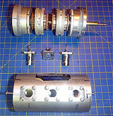
5. Texscan RA5030 / RF557 variable rotary attenuator (2020)
Dual knob rotary attenuator, 0-1.5GHz, 0.5W, 0-50dB in 1dB steps
Problem: Electrical short in certain positions
Repaired: 02/11/20 LIBS6 P.6
Damaged due to being opened by a previous owner unfamiliar with the assembly construction.
Attenuation can be set from 0db to 50dB in 1dB steps. A large inner knob selects 0, 10, 20, 30 or 40dB and this is added to the 0 - 10dB value selected by the small knob on the end.
Externally there is a BNC socket at each end. At some point a previous owner marked the one nearest the knobs Sk2, and the one at the rear end Sk1.
Usually when I dismantle equipment like this I first think how external connectors might affect its construction. It's tempting when noticing 3 screws at each end of its metallic tube, to think all that is needed to pull the unit apart is to undo them with no consideration for the two BNC connectors.
Of course any connections to these must first be disconnected.
It turned out the reason why this didn't work was precisely because the last owner didn't think about this. Result: the BNCs jammed and bent the grounding/EMI fingers on the resistive sections, and the wiper blade on SK1 was bent into a '<' shape instead of '|' which depending on the knob position, was either open circuit or shorted to ground through the fingers.
CONSTRUCTION
Internally the attenuator is realised using two separate sections of resistors that rotate.
Each section has an inner and an outer layer of resistors arranged in a ring.
Each outer end of the resistor sections has a ring of round metal bumps corresponding to each dB position that make contact with a wiper contact blade on an external BNC connector.
The inner end of each section also has a ring of round metal bumps that mates with a central wiper that electrically connects the two resistor sections together.
The central twin wiper assembly mounted on the outside is isolated from the case/ground. Internally it consists of a square spacer of what looks like paxolin between contact blades joined by two rivets, forming an electrical path between the inner rings of contacts on the two resistive sections.
OPERATION
The resistive sections rotate on a concentric spindle. The outer knob/spindle rotates the bottom resistive section to achieve 10dB steps. The inner knob/spindle rotates the top resistive section to achieve 0-10dB steps. The central wiper affectively sums them.
Complete assembly Knobs removed Grey gasket is inert One BNC wiper is bent


Central dual wiper removed Closeup of central dual wiper assembly SK2 0-9dB R section pulls out


SK2 R section removed Sk2 R section outer resistor ring Sk1 x0db range R section


SK1 R section & bent EMI/GND fingers Wipers wrt assy BNC wiper straightended Test setup


Above far right, DAS-45 dc source 1.0000V into Texscan SK2 & top DMM HP3468A; SK1 to bottom DMM Hp3478A.
After
straightening the bent BNC wiper and re-aligning all resistor section fingers, the Texscan now functions as intended, see test results to right, together with my initial sketches:
Refer to table [T14] for the exact resistor values corresponding to the selected attenuation in dB.


TIPS
Replacing the 3.7V 180mA li-ion polymer battery in LCD tweezers:
https://www.ifixit.com/Guide/Smart+Tweezers+and+LCR-Reader+LCR-meter+Battery+Replacement/34548
text
New text box
µ Ω ± ° ⌠ ⌡ ∫ │ ─ √ φ θ Θ ∂ δ ζ ξ ς λ ψ ω τ µ Ω ∆ Δ ∑ ∏ π Ξ ○ ≠ ³ ² ±
text
µ Ω ± ° ⌠ ⌡ ∫ │ ─ √ φ θ Θ ∂ δ ζ ξ ς λ ψ ω τ µ Ω ∆ Δ ∑ ∏ π Ξ ○ ≠ ³ ² ±