8. Pockels Cell Drivers (Q-Switches)
INSTRUMENT REPAIRS & MODIFICATIONS & TEARDOWNS (IN ALPHANUMERIC ORDER)
# Action Status Problem Manufacturer Model Function
1 Teardown Ongoing Research Continuum - Diff avalanche driver assy with pockels cell
2 Teardown ongoing Research Continuum - Mosfet Marx generator Q-switch driver
3 Teardown Ongoing Research Inrad 2-015 Q-switch krytron / avalanche adj 5kV driver
4a Teardown Ongoing Research Inrad 2-017 Q-switch logic & potted adj 5kV EHT PSU
4b Teardown Done Research Inrad 2-017 Q-Switch coupler (pulse inverter)
4c Teardown Onging Research Inrad 2-017 Q-switch 1kV to 5kV avalanche output modules
5 Repair TBD Only 5kV Lasermetrics 8006 Q-switch 10kV AN-7665 hydrogen thyratron driver
6 Repair TBD Only ±1.7kV Leysop M5000 ±2.5kV EO Differential Amplifier
1. Differential avalanche driver assembly with pockels cell
text
2. Continuum Mosfet Marx generator Q-switch driver
text
3. Inrad 2-015 Q-switch driver krytron + avalanche transistors
text
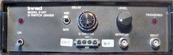
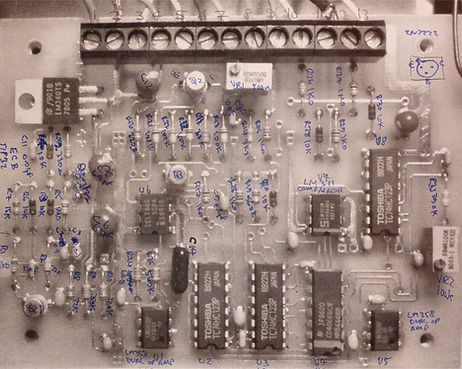
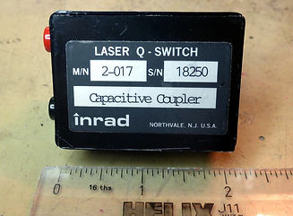
4. Inrad 2-017 Q-Switch Driver (2017)
I bought this because it appeared on eBay in 2016 and I was curious to see how an established laser parts manufacturer would implement a Q-switch driver. The front panel had a connector on it that looked like it supported high voltages, a label on the back said 'Avalanche Driver' and the box was small, I expected to find an avalanche transistor based design inside.
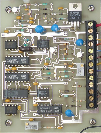
Instead, I found a logic board and a potted high voltage power supply module:


I identified its mating 4-way connector as an AMP MATE-N-LOK series housing part 350779-1, suitable female crimps: 926895-1 (24AWG-18AWG) or 926893-1 (20AWG-14AWG).
I could find no information about it on the web, so I reverse-engineered the circuit board, which turned out to be a non-trivial circuit that still left me scratching my head, although it was easy to work out the front panel controls (above left).
In the reverse engineered circuit below I've used my own component numbering. Pin 1 of the pcb screw block connector is the thick red lead at the end coming from the big off-board 4800µF reservoir capacitor on the +24Vdc supply.
On the pcb, the +24V feeds a +5V 1A regulator powering the logic, and an ICL7660 which generates -5V for the analogue ICs. The circuit consists of 3 x 74HC123 re-triggerable one shots, an HC4066 4 pole SPST switch, an LM358 dual op amp and a LM311 dual comparator, all wired in a somewhat convoluted feedback arrangement controlling a darlington pass transistor that appears to pulse the +24V supply into the EHT PSU.
The VAR / MIN switch determines if the VARIABLE 10-turn helipot introduces an extra delay of approximately 10µs to 500µs between the rising edge of a pulse on the INPUT, to the remaining circuitry that moulds the shape of the pulse presented to the darlington pass transistor that in turn admits the +24Vdc supply to the + input on the EHT PSU (above right).
The LEVEL control sets the acceptable minimum voltage level (0.2V to +15V) for the trigger pulse applied to INPUT.
The TRIGGERED LED flashes for about 25ms when a valid pulse is presented to INPUT.

The MONITOR output is a tap off U2B Q-, halfway through the string of one-shots that control the EHT timing pulse. This output appears to be reliant on a signal presented to the left inner pin on the
4-way EHT connector, which I assume is a safety interlock and whose characteristics are unknown. I could not get this to work (it's pulled up to +5V and simply grounding it had no effect). I did wonder if the equally mysterious one-shot output on the inner right pin was a loopback enable for the input, but they looked incompatible as the output is derived from +24V. Without this enable, Injecting a +3V pulse into the trigger input produced a pulse on the trigger LED but nothing came out of the far left EHT pin on the AMP connector.
Instead, I verified the operation of the EHT supply directly to the base resistor of the darlington bypassing the drive electronics: by adding a socket in place of its driving comparator U1, I injected a pulse from my Wavetek 154 to its output pin 2 and observe high voltage pulses on the unit's EHT 4-way output connector. Surprisingly, the rising edge was around 12ms, the falling edge was several hundred ms, and the shortest time it would allow between pulses was about 2 seconds:


The drive to the EHT PSU is derived from the +24V supply. I tested the supply over a range of input voltages although I could not easily mimic a 24V pulse because even with the introduction of an offset, the maximum Wavetek output pulse I could achieve was 19V, and even this varied over time. I was reluctant to apply dc as I didn't know if it might harm the PSU. Usefully, the Rigol allows selection of probes up to 1000:1 and displays the expected voltage. Thus when used with my Coline 15kV 5MHz probe, the Rigol screenshots above show the actual EHT pulse voltage. As you can see, the maximum measured EHT output for a 19V pulse applied to the darlington base was 3k36V (the exact value varied over time, both from the Wavetek and the EHT PSU). Based upon the table of measured values below, I expect a 24V pulse would produce around 4kV, which is what I would expect for driving a pockels cell.
Wavetek Wavetek = Wavetek EHT PSU output
Voffset PPamp Vpulse -> (Trise 12ms)
1.50V 1.90V = 5V 760V MIN
1.50V 2.80V = 6V 880V
1.60V 3.60V = 7V 1.08kV
2.00V 3.90V = 8V 1.28kV
2.00V 4.07V = 9V 1.32kV
3.20V 5.93V = 12V 2.06kV
3.40V 5.93V = 13V 2.28kV
3.50V 7.00V = 14V 2.46kV
3.80V 7.30V = 15V 2.62kV
2.00V 9.99V = 16V 2.46kV
4.20V 8.70V = 17V 3.03kV
5.00V 9.99V = 18V 3.22kV
Interpolating from above values:
19V 3.36kV
20V 3.50kV
21V 3.64kV
22V 3.78kV
23V 3.92kV
24V 4.00kV MAX
Above - my component numbering
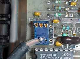
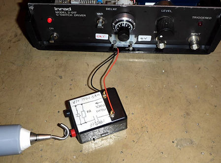
Eventually I replaced all ICs with sockets and verified all the chips worked with my IC testers, and the transistors with the DCA50. Even so, I still could not get it to produce an output by itself, so instead decided to wire the INPUT directly to the darlington transistor base, and the MONITOR to the EHT output, so I could use the 2-017 as a general purpose EHT pulser.
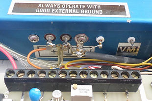
Although I had bought a matching connector and crimps for the 4-way AMP, it was much neater and safer using a dedicated EHT coax that would be easier to route to the small metal box I had planned for my initial, experimental pockels cell driver. The plan was to pulse the 2-017 input as before, and within this EHT pulse, trigger the driver.
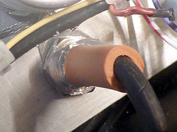
Due to the nature of EHT I was reluctant to simply solder another wire onto the PSU output. Instead I disconnected it from the 4-way AMP connector and routed it to the MONITOR BNC. I was aware dedicated MHV, SHV BNC connectors exist (indeed I already had them on the Wilmore outputs) but I wanted to see if an ordinary BNC could be made to work without flashover. As a first step, I covered the solder joint on the BNC inside the 2-017 with RTV (silicone sealant) and placed a conventional tubular insulator over the RTV before it dried. Next, I disconnected the wire on the INPUT BNC and instead wired it to LM358 U1 pin 2, leading to base resistor R17 on the darlington driving the EHT, so I could inject a variable voltage pulse which would in turn produce a variable EHT output.
Below left: Right & below right:
EHT to RTV insulated BNC INPUT BNC routed to U1 pin 2
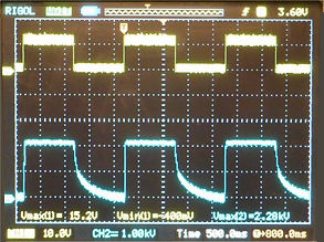
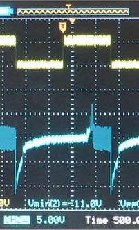
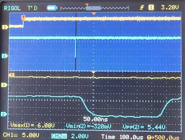
Having checked it worked as before, I fed a 0.5Hz pulse from the Wavetek 154 into the new INPUT BNC (to the darlington base resistor R17, see circuit above) on Rigol top (yellow) channel 1, and with the Coline 15kV probe set to 1000:1 on Rigol bottom (blue) Ch2, I slowly ramped up the darlington volts.
At about 3kV I heard arcing somewhere within the cheap BNC coax cable I was using, visible on the Rigol as the EHT signal repeatedly shorting to ground (which is exactly what is happening) and also corrupting the Wavetek input to the darlington. I reduced it down to an arbitrary 2.28kV and it worked without issue. This is a nice wide operating margin, because the pockels Marx avalanche driver will only need 900V, and I checked that as before, a pulse output around 7V produced 900V.
Below left: Below centre Below right:
EHT output on cheap coax 3kV coax arcs to ground in bursts The coax is happy at 2.32kV


The next step was to wire the TRIGGERED LED circuit back in and modify it to accept pulses up to +24V instead of only +15V as before. A simple remedy was to clamp the input to comparator U7 pin 2, to +5V using a BYV10-140 schottky barrier diode I found in my spares: Vf measured 235mV at 5mA on the DCA75 Component Analyser. I also replaced R29 1kΩ from the INPUT BNC with 10kΩ to keep Vf low and minimise the clamp voltage, further protecting the LM311 input. The TRIGGER LED now flashes as it did before.


4b. Inrad 2-017 Q-SWITCH COUPLER
Some time after buying the 2-017 Q-Switch driver, I saw and bought on eBay USA, a little box described as 'Inrad 2-017 Laser Q-Switch Capacitive Coupler' because I was aware of the need to ensure the pockels cell driver voltage is ac-coupled to avoid darkening or fogging, which occurs when a dc voltage is permanently across the cell, and I assumed this was its function.
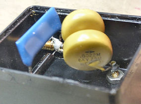
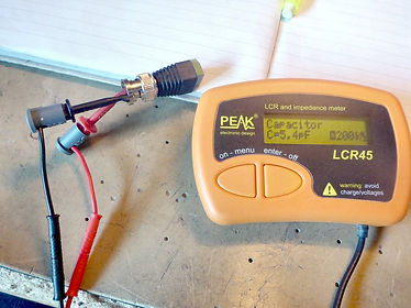
Again I could find no info on the web, so I opened it and found it contained two paralleled capacitors I measured at 1788pF, followed by a 1% 1MΩ resistor (measured in spec at 998kΩ) in parallel with a high voltage clamping diode, its purpose being to clamp positive pulses and let through negative ones, i.e. provide a negative voltage to drive a pockels cell.
Annoyingly, the sockets and terminals are a non-standard 0.1" diameter and I have nothing to fit them. I expect it was intended for direct connection to older pockels cells I have seen with similar looking termninals, but my own Inrad pockels cells have a BNC connector.
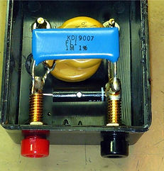


The FL1 is a 1MΩ 10kVdc 1 Watt film resistor manufactured by Aeroflex, no datasheet available.
As expected, when I hooked the Capacitive Coupler up to the output of the 2-017 it transformed the positive output pulse to a (noisy) negative output pulse, but with a 920V output it only dipped to -11V whereas when I omitted the ground and fed in 1.02kV, the capacitors ac-coupled the signal and the full 1.02kV came through.
Below left, Below centre, Below right,
the Capacitive Coupler added 920V in only -11V out 1kV ac-coupled

I wondered if the 1MΩ resistor was too low a value for the PSU output current, so next I tried a few parallel combinations of three 3M3Ω high voltage resistors across the PSU with the output set to 920V. The voltage is much lower because the pulse is a square wave instead of an ac-coupled spike. However It did confirm the PSU output is limited to a few µA, more than likely contributing to the slow rise and fall times:
920V across 1M09Ω produced 2.48V; 2.48V/1M09Ω = 2.28µA
920V across 1M63Ω produced 2.80V; 2.88V/1M63Ω = 1.77µA
920V across 3M26Ω produced 4.24V; 4.44V/3M26Ω = 1.30µA
Below left, Below right,
Checking BNC adaptor capacitance PSU unloaded output is 920V


Above Left, Above centre, Above right,
2 x 3M3Ω in parallel = 1M63Ω 2-017 INPUT 6.8V produces 920V 920V across 1M63Ω = 2.88V
Based upon previous poor experiences with large companies, up until this point I had not thought of contacting Inrad to ask if they could help, but unable to get it to function correctly and with seemingly implausible rise and fall times, I now did this. I was very surprised when they kindly sent me a datasheet for the 2-017 Q-Switch driver and confirmed the intended purpose of the Capacitive Coupler was to produce a negative EHT output. It doesn't appear to work very well at this (although it wasn't designed for this PSU, so maybe that's the problem), but I can still use it to ac-couple the output of my own driver to preserve the pockels cell.
On reading the datasheet, a significant detail came to light: the 2-017 Q-Switch Driver was a 2-part unit that came with an Output Module that plugged into the 4-way connector. Separately, Inrad confirmed the OM contained the avalanche circuit that drove the pockels cell, with my unit simply providing the EHT. I assume the Capacitive Coupler goes between the OM and the cell. Since the 2-017 to OM interface is clearly proprietary they weren't prepared to tell me how to enable the EHT output, so I can justify reverse-engineering their circuit. Eventually I expect I shall work it out.
The manual says the output voltage is set and fixed according to the crystal type and wavelength. Inrad told me "The 2-017 drove a chain of avalanche transistors that were located in a black, plastic box that sat atop the Pockels cell. There were several configurations of plastic boxes that coupled to several variations of Pockels cells. The avalanche transistors were located near the Pockels cell in order to minimize capacitance from a high voltage cable that would slow down the fast transition of high voltage".
What I am calling the interlock input on the 4-way connector feeds into a comparator biased on both inputs, one with VR1 which potentially could select the output voltage. However adjusting VR1 across its range. or applying a voltage between 0V and +5V to the interlock input had no effect. I was able to get the comparator output to a '1' when I put a pull-down on the 'Interlock' input, proving this is the part of the circuit that needs to work, and the PSU then fired repeatedly and erratically but still with long delays of milliseconds between firings, so this clearly is not the solution and instead it must require a dynamic signal i.e. pulse. I may never know how to drive it until I pick up one of the Inrad avalanche drivers.
Something else to try - From the manual, the OM disables the 2-017 when it is absent. I could try a single power-up reset pulse into the Interlock input, that should prime output one-shot U2B for the first shot, and the MONITOR output could be ORed-in to prime subsequent pulses?
Below, excerpt from my notes showing measured timing diagram for the Inrad 2-017:

Above Wavetek rising edge to Monitor O/P
Below Wavetek rising edge to Q1 emitter

The datasheet says the 2-017 driver can run at 2kHz and the recovery time is 100µs with a 25pF load, but my own measurements show the EHT rising edge to be 12ms and the trailing edge significantly longer when running into my 3pF D-dot (the Coline 15kV probe is also only 3pF). Even with the OM providing the real avalanche circuit, the EHT PSU is pulsed by one-shots with delays in the region of 100s of µs, not tens of ms, and to achieve a 2kHz rate requires it to switch on and off within 1/2000 = 500µs, suggesting my PSU may be faulty.
What is puzzling is all the effort to produce such short pulses when the PSU can't work that fast. Maybe pin 7 on the 4-way EHT connector is actually bi-directional: maybe this is an output that triggers the short OM avalanche pulse, but after that the OM biases pin 7 to keep the PSU on for successive pulses?
Regardless, this is of no significance to me. I originally bought it out of curiosity, and when I realised it only had slow edges, I decided I could use it as a variable EHT supply to test my own avalanche driver design. Now reading the datasheet, I found Ironically I had decided to employ it in a manner similar to Inrad's intended use.
The question remains whether the low µA output is normal and if this will adversely affect my experiments.
4c Q-switch avalanche output modules
5. Lasermetrics 8006 10kV Q-switch driver AN-7665 hydrogen thyratron
text
6. Leysop M5000 ±2.5kV Electro-Optic Modulator Differential Driver
text
New text box
µ Ω ± ° ⌠ ⌡ ∫ │ ─ √ φ θ Θ ∂ δ ζ ξ ς λ ψ ω τ µ Ω ∆ Δ ∑ ∏ π Ξ ○ ≠ ³ ² ±