Rising to the challenge, I tried to repair it by touching the wires together and securing them with epoxy resin whilst holding the wires in place with a generous lump of Blu Tack.
5. Lyons Instruments (UK) PG73N Dual Pulse Generator (0-10MHz) (2016)
I obtained three of these in faulty condition together with a paper service manual, see [I30] bottom of this page, ultimately to control the timing for the LHC project.
I already owned an ubiquitous Continental Specialities Corp (CSC) 4001 0-5MHz pulse generator, but the LHC needed more than just one channel. Besides, this instrument is in a plastic case, susceptible to external influence. At least its design is based on the reliable 74LS123 dual retriggerable one-shot.
I had originally thought of using PIC microcontrollers for LHC hardware timing but software-derived timing is susceptible to EMI pulses such as those emitted by flashlamp pulse drivers and whilst my design pays good attention to EMC, it seemed better to me to start with hardware derived timers in the first place, particularly as it was cheaper to buy PG73Ns than build the hardware myself. The dual 10MHz outputs go to ±10V.
DOCUMENTATION
#1
Physical inspection
'M.LEWIS' scratched into front left of top aluminium strip but otherwise remarkably clean;
One switch loose


Functional inspection & repair
(a) Fuse ok.
(b) Signs of functional activity on outputs.
(c) Checked all cap ESRs - ok.
(d) All dc supplies in spec.
(e) Channel A NORM/COMP toggle switch broken - replaced, below:.


(g) Power toggle switch broken - replaced, below:


(h) Output pulses erratic, B normal output stuck low, one-shot non-functional:
IC 'F' 74S00 tested ok on my digital IC tester [I42], but in use caused sporadic events. Replaced.
(i) The one-shot push button didn't work. Re-soldered its Period selection switch - fixed.
The chips are dated 1981 so it's pretty old, and old solder tends to crystalise.
Re-soldered all dry looking solder joints on pcb, switches and pots.
(j) Found a 100nF disc de-coupler with a loose leg on the bipolar output pcb - re-attached, below:


After these fixes the instruments worked. I ran through the calibration procedure and found some of the range limits were out by about 10%, but of no inconvenience to me.
Lastly I fixed the mechanics:
(k) Swapped front top left scratched aluminium plate to underside.
(l) The left outside panel came away - turns out it was glued to a piece of wood! Re-glued.


This instrument is now operable.
#2
Physical inspection
Generally in good shape.
Red ink on front panel near power light, saying the light doesn't work.

Functional inspection & repair
(a) Fuse Ok.
(b) Limited functional activity on outputs.
(c) Checked all cap ESRs - ok.
(d) No Channel A output.
+15V 1A IC regulator Fairchild LM340KC-15 (7815) on P96 Chan A only producing +1.38V.
These are usually bullet-proof so wired lab supply in its place to confirm no load issues.
Next wired 56Ω (~270mA) power resistor in place of load and confirmed regulator faulty.
Lyons PG73N #3 has a +15V 450mA IC regulator SGS L037T1 (see [D39], bottom) in
the same position so I replaced it with one of these as I had bought a joblot of 4 for repairs.
Confirmed reappearance of +15V supply and Channel A output now present:


(e) Channel B positive output but no Channel B negative output.
The circuit (see back of manual [I30], bottom) uses a National Semiconductor LM340T-15 +15V
positive voltage regulator to produce -15V, which is a valid application, see data sheet [D40],
bottom. However this regulator was faulty. Replaced with LT037T1 +15V regulator as #1 also used
one here. Confirmed re-appearance of -15V supply and Channel B negative output now present:


(f) Power switch lamp does not work.
This is within a sealed plastic tube, its wires leading directly
to the transformer secondary marked 19V 0.45A.
That's 1/3 of the entire unit's consumption! What a waste of
power and unnecessary heat. The rest of the instrument runs off
the other secondary marked 19V 1.0A.
Here's a joke: How many hours does it take to change a light bulb?

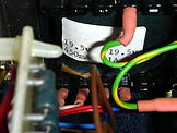
Cutting open the tube with a knife revealed a 'grain of rice' glass filament bulb with one wire snapped off at the glass. Measuring 21Vac across them, it still worked when I touched it back.


It worked but quickly failed, doubtless due to bulb heat softening the epoxy. The lamp wire appeared intact so the gap was microscopic. I immersed the gap in a large blob of conductive silver paint which worked for a few minutes before again failing.
Next I did what I should have done in the first place: replace it with a 3mm ultrabright white LED limited by a 1kΩ miniature C3 resistor to a convenient +5V (3.3mW), saving 8.5W of heat.


Now there is a spare winding that could be used for a 24V fan but I would have to cut a hole in the box, so we shall leave it unless the regulators blow again. If that happens I will replace all power lamps with LEDs.

This instrument is now operable.
#3
Physical inspection
Generally in poor shape, with filthy front panel.
This had been dropped (known at purchase). The case was loose and rattling, with the left handle missing, and its top aluminium support bent downwards about 30 degrees.


Functional inspection & repair
(a) Fuse Ok.
(b) Limited functional activity on outputs.
(c) Checked all cap ESRs: C47 shorted, 47µF 25V. Replaced. IT WASN'T C47 (TOO SMALL) CHECK LOGBOOK
(d) Channel B positive and negative outputs ok.
(e) No Channel A output.
Bottom right +15V 450mA IC voltage regulator L037T1 [D39] on P97 output too low.
Wired lab supply in its place to confirm no load issues, confirming faulty regulator. Replaced.
Confirmed re-appearance of +15V supply and Channel A positive output now present:


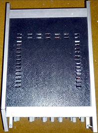
(f) The electronics slides out of the box on blue plastic runners, which also have embedded threads
to secure the front and rear panels. The runners had come away from their surfaces, some were
cracked, and a portion of one was loose in the box (see physical inspection top right photo).
I stripped the case and glued the blue strips where they had cracked, re-arranged the broken runner
and glued all strips back and re-assembled the unit. I was lucky to straighten the bent aluminium
handle support spar without it snapping.


ADD PHOTOS OF SIDE SHOWING STRAIGHTENED SPAR 705j311, 705j312
(g) Missing RH handle.
Given the age of the equipment it was perhaps no surprise the mechanical stuff is based on imperial
units: I measured a handle and its mounts and found it consisted of a 1/4" OD aluminium rod within
a 3/8" ID solid black plastic tube. It's hard to find any imperial rods or hard tubes in the UK but
close metric alternatives were to hand; 3/8" is close to 10mm and 1/4" is a little over 6mm [T3].
I couldn't find any hard tubes on eBay UK, but 10mm OD / 7mm ID nylon black hose was near enough,
together with a short length of 6mm OD aluminium rod.


(i) Missing Period selection switch knob cap replaced with similar item from my widgets box.
REPLACE THIS WITH PHOTO OF UNIT AFTER HANDLE REPLACED:

This instrument is now operable.
FURTHER IMPROVEMENTS
Even if the regulators don't blow, I may replace all power lamps with white LEDs as with #2. When I do this I'll also consider fitting a fan to each unit. I say consider, because the easiest mechanical solution would be to add the fan on the left side of the box in the main pcb area, but I would not want to introduce an airflow that could add thermal noise leading to electrical noise in the oscillator. Even blowing out rather than in would still lead to a turbulent warm airflow over the pcb.
Whist investigating #2's regulator fault I looked for hot components using my Magnavox MVX48 thermal imager, right. This revealed most heat in the transformer, bad regulator, and the bipolar output driver pcb located on the far right in the case. Looking at the circuit, this may be due to both transistors in the totem pole push-pull output never turning off completely.


Now the faulty regulator has been replaced and the transformer is no longer wastefully powering an 8.5W incandescent POWER ON lamp, if I decide to fit a fan I will look again at the thermal signature. It may be better placing a smaller inlet fan on the far right, in the small metal compartment behind the the regulators that houses the transformer and rectifier & smoothing pcb. Top cover case convection perforations do cover this area, see initial inspection photographs of #3, above.
New text box
µ Ω ± ° ⌠ ⌡ ∫ │ ─ √ φ θ Θ ∂ δ ζ ξ ς λ ψ ω τ µ Ω ∆ Δ ∑ ∏ π Ξ ○ ≠ ³ ² ±