7. DIY Rubidium Oscillator (2023)
Obviously this is not a Rubidium oscillator built from scratch. Instead this is an OEM oscillator housed in a box with a quad channel distribution buffer and suitable power supplies.
Late 2022 I bought a used Datum Efratom LPRO-101 10MHz Rubidium Frequency Standard for $200, after watching the following video: https://www.youtube.com/watch?v=zW5ffFuEQsw
I'll use this as the reference frequency for all of my test equipment that accepts an external source, and as an absolute frequency reference for all precision timing.
I'm not that familiar with the models but it seems likely this is an early one (the 2017 video above says they were then on eBay China for $60). In 2022 the LPRO-101 is a rarity on eBay China which mostly seems to have expensive (Morion) FE-5680As and those I've seen have a more fiddly distributed power pinout requiring 15V & 5V PSUs vs a simple 2-pin 24V supply for the LPRO-101.
Here's an excellent video comparing stability of a FE-5680A vs an OCXO:
https://www.youtube.com/watch?v=CqR6dqPW3Vw
LPRO-101 repair guide: https://www.changpuak.ch/electronics/ocxo/Efratom_LPRO_101_Repair_Guide.pdf
I came across a 2012 review of a FE-5680A by Squeaky Dave [see footnote] and was surprised to find the signal was a rather poor sinewave (18:35): https://www.youtube.com/watch?v=I55uLRRvLCU
The following very informative website goes into more detail, explaining 'While the crystal filter removes frequency components not related to 10 MHz, not much attention was made to keeping the various follower stages in the linear range so the 10 MHz output waveforms are somewhat clipped, introducing harmonics' and the FE-5680A emits low level noise spurs as a result.
He adds, by comparison the LPRO-101 is 'extremely clean and I think that there was just little bit of "digital sounding" noise on the LPRO-101 that I'd not really noticed before':
https://www.ka7oei.com/10_MHz_Rubidium_FE-5680A.html
However an RF designer friend pointed out it is advantageous to have a certain amount of linearity in the zero crossing point to ensure accurate switching, so the less than perfect sine may be deliberate.


SIGNAL OUTPUT
The datasheet for the LPRO-101 says its 10MHz O/P signal is 550mV rms (~1.6Vpp) into 50Ω.
http://www.referencedesigner.com/rfcal/vrms-to-vpeak-conversion.php
My SA44 Signal Hound spectrum analyser [I147] accepts an external 10MHz reference of >0dBm (224mV rms) to +20dBm (2.24V rms) max, recommended 13dBm (~1V rms). http://599.cz/storage/USB-SH44_manual.pdf
https://coretechgroup.com/dbm-calculator/
I have no manual for my Ballantine 6130A Time Mark Generator but on the back it says its external 10MHz reference I/P accepts 2Vpp (707mV rms).
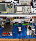
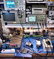
INITIAL TEST
I made an initial test connector for the LPRO-101 using square pad prototyping pcb. I added a dual row 0.1" pitch socket to it together with an SMA for the 10MHz output, test points for the lamp (YW) and crystal (BE) output voltages, and a super bright LED to the BITE OUT OF LOCK signal.
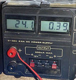
I found a long and heavy flat heatsink in my spares and placed the LPRO-101 on top, hooking it up to a 24Vdc bench supply,
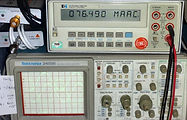
After checking connections I applied power and observed ~1.2A taken from the 24V dc supply. The LED came on and extinguished after a few minutes, and my then uncalibrated Racal 1998 counter eventually displayed a solid 10MHz signal. At this point the supply current had dropped to ~390mA.


SELECTING A BOX
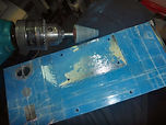
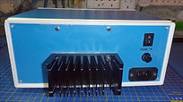
The manual for the LPRO-101 recommends the metal case of the oscillator module is kept isolated from any grounds. Given a large heatsink needs to be added to its hot baseplate and access is required to the other side for its tuning aperture, this could be fairly tricky to mount in an instrument case but a while back I bought a 250 x 190 x 110 blue metal/plastic enclosure from eBay China for £17. The plastic bit is the surround to the front and rear panels, resulting in these panels being electrically isolated.
Ordinarily this would not be a good idea, but by pure chance the LPRO-101 is a perfect fit in the plastic frame. Oddly the front and rear panels are 0.5mm thick steel, not aluminium. Steel provides greater structural integrity but is difficult to machine and with only basic tools at my disposal, mistakes are hard to correct.
POWER SUPPLY
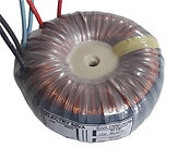
According to the manual the LPRO-101 takes about 1.7A until locked and ~0.5A thereafter. I had observed lower currents in my initial test, but this could change depending upon external temperature. It is also sensitive to magnetic fields and initially I planned on using a large 100VA 24V toroid transformer I had in an IP box, the toroid also offering lower noise than a conventional transformer.
To save the effort of building a 24Vdc 2A regulated supply I went to eBay China where the best PSU power/cost compromise was a $20 7.5A rectifier/LT1083 linear regulator which added a wide margin for dissipation in a non fan-cooled box.
I hooked the big toroid up to the PSU to run more tests but its 24Vac output produced 32.5Vdc [C11c] which added unwanted heat to the PSU heatsink. The power was also twice what I needed and it was a bit too big for the box. The lowest voltage I felt I could get away with was 20Vac which produces just under 27Vdc, and 50VA was just about right. The closest I could find on eBay UK (£20) had two 20V windings, but I could wire them in parallel.
[C11c] https://www.petervis.com/electronics%20guides/calculators/transformer-ac-to-dc/ac-to-dc.html


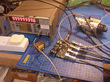
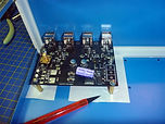
10MHz 1:4 DISTRIBUTOR BUFFER
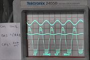
In the same week I spotted and bought a 4-channel 10MHz distribution board on eBay UK for £20. All it said was it accepts a 30mV to 100mV 10MHz input and runs off an ac or dc supply of no more than 7.5V which should be separate from the one powering the frequency source. Having a small 6Vac 250mA transformer in my spares and no wish to build another PSU, I fed the ac into the board and hooked up the oscillator.

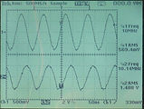
The Racal 1998 indicated a locked signal and I thought all was well but I discovered all of the distributor output waveforms were distorted. The transformer winding is 6V-0-6V so I had only used one winding which meant half the current and I wondered if I was overloading it, but found only 77mA taken.


Tracing the distributor supply I found a bridge rectifier feeds into a 7805 DPAK +5V regulator powering all ICs but no rectifier reservoir capacitor, resolved by adding a 470µF electrolytic across the bridge.
Attaching the LPRO-101 to it via a variable attenuator, the optimum input with least output distortion was ~40mVrms. I will add a 30dB fixed attenuator between the LPRO-101 500mV O/P and the distributor I/P.

FITTING IT ALL INTO THE BOX
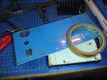
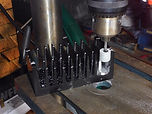
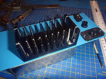
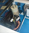
To keep the PSU electrics together I decided to mount the PSU on brass spacers above the toroid. In the photo below left, all components are loose and no holes have yet been drilled in the case.
This layout keeps the LPRO-1010 connector away from the mains wiring, transformers and heat from the PSU, and close to the distributor board input whilst also permitting calibration from the front panel.

At first I was going to fit an IEC mains inlet/filter/fuse/switch combo from my spares but its metal case would have shorted the rear panel to earth.
Instead I found the best physical arrangement was to use separate parts (the way over spec 16A filter was once in a washing machine).
21
ADD PHOTO OF FILTER
LPRO-101 COOLING
A Rubidium oscillator contains a heater and the LPRO-101 datasheet indicates it dissipates ~12W at its optimum operating temperature of 25°C which is the point of minimum deviation from its frequency.
An internal fan on the LPRO-101 could introduce noise from the varying airflow so I'm using a convection cooled external heatsink instead. The LPRO-1010 datasheet recommends a thermal resistance of <2°C/W.
I had no idea of the °C/W thermal dissipation of the large heatsink I started with, but I got a reasonable idea from the following online calculator at various airflow rates:
[C37] https://myheatsinks.com/calculate/plate-fin-heat-sink-calculator/
W 200mm Answers:
L 70mm Airflow Rate Thermal Resistance Pressure Drop Base Temp
H 40mm 0.5 m/s ( ~100 LFM) 0.56 °C/W 768.5 Pa ( 3.084" H2O) 31.7°C
Base 10mm 1.0 m/s ( ~200 LFM) 0.29 °C/W 1,582.0 Pa ( 6.349" H2O) 28.5°C
Fins 3mm #20 2.0 m/s ( ~400 LFM) 0.16 °C/W 3,341.3 Pa (13.409" H2O) 26.9°C
Power 12W 4.0 m/s ( ~800 LFM) 0.09 °C/W 7,400.3 Pa (29.699" H2O) 26.1°C
Tamb 30°C 5.0 m/s (~1000 LFM) 0.08 °C/W 9,681.6 Pa (38.855" H2O) 26.0°C
General info: https://www.engineeringtoolbox.com/convective-heat-transfer-d_430.html
LPRO-101 BASEPLATE HEAT SPOTS
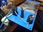
Viewing the baseplate on my MVX-48 thermal imager [10: Other Instruments], heat is concentrated around the oscillator near the top left of the baseplate in the reverse photo below, i.e. near the tuning hole in front photo above.


PUTTING IT ALL TOGETHER
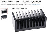
As I explored where to mount the heatsink and IEC inlet components, it soon became apparent the fragile nature of the case meant it would likely bend under the weight of the sink, which is obviously far larger than required. The LPRO-101 manual recommends any external heatsink covers the entire backplate to spread the thermal load but once I'd identified the thermal hotspots I reckoned I could deviate from this and fit a smaller heatsink. I didn't want to chop up the big one so I bought a Fischer Elektronik SK92-50-SA 100x50x40mm 1.75°C/W instead, also making it much easier to mount the other parts.

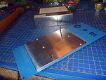
The backplate is secured using Six 4-40 UNC screws. To drill the steel back panel precisely to fit it, I placed a paper baking sheet over the backplate and pencilled the holes to determine their centres, then laid the paper over the panel and set the hole centres with a punch.
Ordinarily I would keep thermal interfaces to a minimum and originally I planned on cutting a hole in the rear panel to mount the big heatsink directly on the LPRO-101 baseplate lamp section using its 4 screws, securing the top half to the case with the remaining 2 screws. However this would have overstressed the 4 tiny self tap screws that hold the panel in the 4 corners of the plastic surround so I abandoned this idea, but then junked the big heatsink too. By the time I got the small heatsink I had long forgotten the sensible thermal plan to cut a hole in the steel back panel for it.
A quirk of the case/LPRO-101 mechanics is a 4mm gap between the LPRO-101 baseplate and the case rear panel because the LPRO-101 abuts the plastic frame rather than passes through. I now filled this gap with a 4mm aluminium plate cut to size and added thermal grease to all surfaces, thinking this might have better thermal conduction than a strip of Bergquist material; certainly cheaper.
At this time it hadn't occurred to me the quirk meant the plastic frame, which is also screwed to the steel case bottom, would now provide additional support for the LPRO-101, probably because I had just discovered how hard it was to cut the steel accurately for the IEC components using just drill bits and a file.


32
ADD PHOTO SHOWING SPACER IN PLACE
The remaining top 2 screws on the LPRO-101 secure it to the steel case rear panel. It was particularly difficult to remove what I assume is stove-enamelled blue paint on the rear panel. Ordinary paint stripper had minimal effect (It’s now illegal to use paint stripper that contains dichloromethane unless you have done an expensive course and sat an expensive exam. You can get paint stripper with the dichloromethane taken out, but given that it’s the dichloromethane that actually strips the paint, those ones are a bit pointless. https://robomofos.com/blog/) but leaving it overnight did soften it up for a pointed Dremel grindstone on the end of my vintage Black & Decker drill.


Mounting the heatsink presented its own difficulties: I could align the fin gap with the 2 vertical mounting holes on the left end but not the other. The only option was to saw along the fins top and bottom and prise off the outer edges of the last fin on the right end to make space for its 2 mounting holes. My crude tools consisted of a hacksaw, hammer, pliers, Dremel miniature grindstone wheel (on my Clarke pillar drill) to flatten the remaining aluminium, and a black Sharpie to hide the evidence.

I also removed paint to earth all metalwork within close proximity of mains, the exceptions being the front and rear panels and the distant top right spar supporting the lid which I earthed separately.


FINAL ASSEMBLY
Once I had the LPRO-101 secured in the box I finalised the positions of the other components. I removed the I/P BNC from the distributor board and added a vertical SMA in its place. I added brass supports to the distributor board and adhesive paper labels to the front panels so when I pushed the board up against it in the box, I could pencil around the BNCs and thereafter work out their centres for drilling. With the BNCs pushed through the front panel, I repeated the exercise for the brass supports.


In the background I modified the custom connector I built for the LPRO-101m, rotating the SMA 90 degrees so it now faced towards its top. I added additional leads to take the lamp and crystal voltages to 4mm sockets on the front panel, the 'OUT OF LOCK' BITE signal to an LED, and another for PSU 'POWER ON'.
Lastly I wired up the IEC components and the mains transformers, adding extra shrink wrap tubing to the crimp insulators to prevent exposure to the surrounding metalwork that I had earlier earthed.


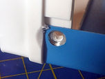
I arranged a small gap between the transformers to allow a 5mm diameter Perspex tube to run from the LPRO-101 tuning hole to the front panel. This tube has a modified nylon pot tuning tool on one end that fits into the LPRO-101 tuning hole (the tuning screw is particularly thin), and a screw on the other end held within a 5mm LED holder attached to the front panel, allowing the LPRO-101 to be calibrated from the front panel. A spring and O-ring keep the tube pressed against the tuning hole, see photos below.
REVISIONS
THERMAL INTERFACE
Temperature measurements now indicate the maximum temperature is on the PRO-101 top surface above the lamp, little different to how it measured when I had it on the bench simply resting on top of the big heatsink. This is unsurprising given the earlier poor choice of sandwiching low thermal conductivity steel between the aluminium heatsinks together with multiple layers of TIM.
At the time I knew steel has poorer thermal conductivity than aluminium, but I failed to check just how bad it actually is. Having now done this [T17], I was also surprised how poor TIMs are at thermal conduction. I now have very low thermal conductivity 54K W/m steel sandwiched between two blocks of aluminium 240K W/m, degrading the transfer to the external heatsink by a factor of four, all glued together with ~1K W/m thermal paste which by comparison is a thermal insulator. It's also Chinese steel, so probably worse than 54K W/m. This arrangement clearly has to go.
Now the LPRO-101 is firmly retained by the plastic frame, I must go back and either cut a hole in the steel rear plate to directly mount the heatsink on the LPRO-101, or the aluminium spacer plate, or simply start again with a fairly thick aluminium panel in place of the steel panel which I can use as its cutting template.
Additionally, in my haste to install the LPRO-101 I decided to fill the gaps in what looked like old pitted Bergquist-like TIM on the LPRO-1010 baseplate with conventional heatsink compound rather than attempt to remove the original TIM. Now I have to revisit the thermal design, I should remove this too. It shouldn't be on top of existing TIM and I expect it's far thicker in the gaps than the 100µm needed.
Another issue is thermal paste dries out and has to be replaced every 5/6 years (if your PC fan has got louder over the years, it may be fighting harder to cool your CPU if its TIM has dried out). Initially I thought of replacing my old RS ~1K W/m TIM grease with soft 86K W/m indium foil but when I tried to use this to cool a PC CPU I found it made it hotter, probably due to air pockets that are more readily avoided when using TIM paste.
2023 UPDATE
Having compared thermal conductivity, hardness and prices of various TIMs I settled on graphite sheet which I found offered for PC CPUs at $3 on eBay China:
https://en.wikipedia.org/wiki/Mohs_scale
https://en.wikipedia.org/wiki/Hardnesses_of_the_elements_(data_page)
Material Sym W/m, K Hardness Mohs Price (eBay 2023) AWG
Aluminium sheet at 127°C Al 240 2.75 $2 100 x 100 x 1.00mm 18
Copper sheet at 127°C Cu 302 3.00 $2 100 x 100 x 0.05mm 30
Gold sheet at 127°C Au 312 2.50 $167 25 x 25 x 0.05mm 30
Graphene sheet (C) 400 9.00 $105 100 x 200 x 0.05mm 30
Graphite sheet (C) 168 1 - 2 $3 100 x 100 x 0.05mm 30
Indium sheet In 86 1.20 $30 100 x 100 x 0.05mm 30
Lead sheet Pb 34.7 1.50 $24 12" x 36' x 0.80mm 21
Silver sheet at 127°C Ag 420 2.50 $84 100 x 100 x 0.05mm 30
Tin sheet Sn 67 1.5 $10 100 x 100 x 0.03mm 30
Thermal adhesive, ceramic filled - 1.5 - $10 (Arctic Silver 2.7g)
Thermal adhesive, silver filled - 8 - $10 (AS Ceramique 2.7g)
Thermal grease - 0.5-7.5 - $3 generic, 1g
REFINEMENTS
There are no gain adjustment pots on the distributor board and the levels on all 4 outputs vary wildly. Whilst this is of less importance provided the minimum reference output voltage is met, I would prefer they were closer. The output signal is also noisy and tracking on the board suggests it has been clumsily laid out by a PCB auto-router with no ground plane or star-pointing of return grounds. It was after all a bargain at £20.
I'd like isolated outputs, also absent, all of which means it looks likely I shall build my own board to replace it and I'll probably have to replace the BNCs with alternatives having insulated mounts.
Many isolated designs exist on the web, most using expensive 1:1 50Ω RF transformers, typically Mini-Circuits T1-6-X65 or Coilcraft SWB-3010. Paul Versteeg's GPDDO isolated distributor uses cheaper
PE-65612 DAT transformers but these are typically used with low current TTL logic and aren't guaranteed to meet 50Ω currents (his design is itself derived from the TADD-1 6-channel RF Distribution Amplifier which uses Mini-Circuits 50Ω T1-1-X65) https://www.paulvdiyblogs.net/2020/07/ Having said that, DAT transmission lines are typically 75Ω to 100Ω at higher voltages, so theoretically should still be ok.
Another aspect of the design of a replacement board is although the signal is only 10MHz, fairly fast slew rate op-amps are required to accurately reproduce what should ideally be a symmetrically clipped sinewave. Thus, designs on the web employ fast op amps that are not particularly cheap:
Nat Semi LM7171: 200MHz, 4100V/µs
Analog Devices AD8055: 300MHz, 1400V/µs
Maxim MAX4384: 210MHz, 485V/µs
Runic RS8752: 250MHz, 180V/µs (on the distributor board I bought)
From my RF friend: A rule of thumb to determine slew rate, is at least 2 x π x freq x required peak amplitude: e.g. 10MHz at say 1V peak; 2 x π x 10MHz = 62,831,853 V/s then divide by 1^6 to get V/µs
which is 62.8V/µs minimum. Allowing some headroom, aim for around 100V/µs.
Footnote:
I call him Squeaky Dave but I have the utmost respect for him. Tt's just his voice gets me every time...
text
text
⌠ ⌡ ∫ │ ─ √ φ θ Θ ∂ δ ζ ξ ς λ ψ ω τ µ Ω ∆ Δ ∑ ∏ π Ξ ○ ≠ ³ ² ±