7. Non Linear Optics (NLOs)
NLOs are typically salt crystal compounds that change the wavelength of light passing through them. The change is usually associated with the way in which the crystal lattice is cut to shape, the temperature of the crystal, the angle of the crystal with respect to the input signal, and its phase.
Multiple NLOs can be run in series, further manipulating the original signal, but each NLO considerably saps the power of the input signal resulting in a much weaker output. Manipulation can take many forms, utilising different NLO variants, from simply halving the wavelength (harmonics) to summing wavelengths or even producing entirely new, tunable wavelengths. Project DUV generation largely borrows from paper [O12] which utilises all of these variants and I had to consider their viability in some depth. Refer to [References: Glossary] for simple definitions of the most common NLO variants.
From my research on spectral enhancement, initially I decided the project would combine NIR 1064nm with DUV, the optimum wavelength being 193nm. However as years passed I realised very few optics are available on eBay for this wavelength, and I never saw a summing NLO for 193nm. In fact over more than a decade, I have never seen any NLO described as an SFM on eBay.
Crystals can of course be bought new. I found Chinese company HG Optronics (http://www.hgoptronics.com) very willing to sell them to me at a reasonable price, but I lack the knowledge to specify their complex chemical and physical properties. Elsewhere I found a new fully specified 193nm SFM but with shipping and import duty added it would be around $1700 (and 2130nm wasn't close enough anyway):
ESKMA Optics, Lithuania, BBO SFM 213nm + 2130nm to 193nm, part# BBO-0423-03H €1135 (Mar 2019)
http://eksmaoptics.com/nonlinear-and-laser-crystals/nonlinear-crystals/beta-barium-borate-bbo-crystals
Much as I would like to produce 193nm, I would have to specify and purchase the SFM and OPO from new, way beyond my knowledge and pocket. Selecting NLOs is something of a chicken and egg situation to the unqualified, but I had to start somewhere.
ND:YAG LASER POWER
My first step was to determine the amount of power the new Nd:YAG would require. Although I knew I had very little chance of producing 193nm I decided to factor it in as a potential wavelength and based the power I would need upon what I perceived might be produced were I able to do so. I found a label on an old laser on eBay:
Quantel Big Sky CFR 200 laser (manf 2012):
1064nm 250.0mJ
532nm 150.0mJ 150/250 = 60% power = 40% loss wrt 1064nm
266nm 50.0mJ 50/250 = 20% power = 80% loss wrt 1064nm (50/150 = 67% loss wrt 532nm)
Paper [O12] used a 700mJ 8ns 8mm 1064nm laser to produce 0.4mJ at 193nm, reducing the pulse to 3.5ns, which when focused to 70µm produces 3GW/cm² on a par with an excimer laser.
Obviously I would reach nowhere near the efficiency these researchers achieved, even using good quality crystals from an industrial laser, but if I could focus my LIBS beam to 50µm and reduced my requirement to 0.2mJ at 193nm I felt this should go some way to make up for my inefficiencies.
Having no figures on the efficiency of generating 213nm, but based on what I had read in papers and how the Quantel values decreased with wavelength, together with figures from paper [O12], I plucked some figures out of the sky with deliberately lower conversion efficiencies:
Mine:
1064nm 1J
532nm 500.0mJ = 50% loss wrt 1064nm
266nm 100.0mJ = 80% loss wrt 532nm
213nm 10.0mJ = 90% loss wrt 266nm
193nm 0.2mJ = 98% loss wrt 213nm
A 1J Nd:YAG seemed a good start. Even if I could not produce 193nm, I should at least be able to produce 213nm with quite a bit of power, and I noted I would have to build some kind of output power control into the laser as well.
Eventually I found a seller on eBay offering ex-medical Nd:YAG resonators coupled with Kaiser LS1000 PSUs he had modified, together with photographic proof of operation. The label had a familiar manufacturer's name on it which gave me added confidence: Kigre MK580. Rather than attempt to build my own resonator and align it, I opted to buy the assembled Nd:YAG.
NLO HARMONICS
Laser harmonic generation from multiple wavelengths obeys the same reciprocal summing law as for resistors in series: 1/H1 + 1/H2 = 1/H3.
Thus,
(a) 1/1064nm + 1/532nm = 1/355nm (strictly speaking it's 1064/3 = 354.7nm)
(b) 1/1064nm + 1/266nm = 1/213nm (212.8nm)
(c) 1/532nm + 1/355nm = 1/213nm (212.9nm)
The SFM setting on this OPO calculator [C29] can be used to determine this:
https://www.photonicsolutions.co.uk/nonlinear.php
Paper [O12] describes 193nm being generated from 2074nm + 213nm (2074nm is generated from an oscillator seeded by 532nm): (1/2074nm + 1/213nm) = 1/193nm. They were able to use a specially bought crystal
(b, above) to remove a crystal stage in their generation of 213nm, but I would have no such luck
(c, above). If I was going to produce 193nm from 213nm, this would necessitate another crystal stage:
2HG 532nm 1 crystal (1064nm -> 532nm)
3HG 355nm 2 crystals (1064nm -> 532nm) + 1064nm -> 355nm
4HG 266nm 2 crystals (1064nm -> 532nm) + (532nm -> 266nm)
5HG 213nm 3 crystals (1064nm -> 532nm) + ((1064nm + 532nm) -> 355nm) -> 213nm
THG 193nm 4 crystals (1064nm -> 532nm) + (532nm -> 2074nm) + ((1064nm + 532nm) -> 355nm)->213nm ->193nm
(THG usually refers to Third Harmonic Generation, but in this case I'm using it for The Holy Grail)
Running the reciprocal rule for all harmonics, I also found 700nm + 266nm -> 193nm which saves a crystal, but necessitates using a separate laser to generate 700nm. I identified potential lasers as Ti:Sapphire and Alexandrite that could be tuned to 700nm.
Of further note, why does it have to be exactly 193nm? 193nm is simply the fundamental of an ArFl laser. If I could find an affordable SFM summing crystal, I could add 266nm + 694.6nm ruby
(synchronously Q-Switched) = 192nm. Similarly 266nm and 680nm (Alexandrite CW) = 191nm, but I would not want to go lower, as that would enter the even more complex realm of vacuum UV.
Of these, ruby seemed the most promising because the tuned lasers were at the edges of their power bands at 700nm.
If by its nature ruby is unsuitable, but I could find an affordable SFM summing crystal to add 266nm and 750.4nm (tuned Alexandrite peak power: [O21], High output energy tunable Alexandrite laser), I could generate 196nm.
Alternatively synchronisation could be attempted with a CW Alexandrite laser pumped by 532nm from the Nd:YAG: this paper managed 'Output power of 2.6W at 755nm and tunability of 85nm were achieved using 11W of pump at 532nm: [O23], High Power Continuous-Wave Alexandrite Laser with Green Pump. The Alexandrite rod would also benefit from being warmed by the water coolant coming from the Nd:YAG.
After all of my head scratching above, I finally found this 2017 paper describing exactly what I had in mind to produce 193nm using SFM Nd:YAG 4HG & Ti:Sapphire and alternatives:
[O24], High power, narrowband, DUV laser source by frequency mixing in CLBO. It says mixing 266nm with Ti:Sapphire at 706nm will be low power due to using BBO ([O12] got round this by cooling the BBO) however I think this is more down to Ti:S 706nm being at the end of its range where power is lowest; its peak output is 760nm, which would yield 197nm. Instead they finish with a Ti:S design similar to [O12] that has a range from 193nm to 196nm.
I assume they used Nd:YLF in place of the more common Nd:YAG because the latter's 2HG is 1064/2 = 532nm
which is right on the edge of the 450-532nm Ti:S absorption band, whereas Nd:YLF 2HG is 1047/2 = 523nm which is a little closer to the Ti:S peak absorption of 495nm.
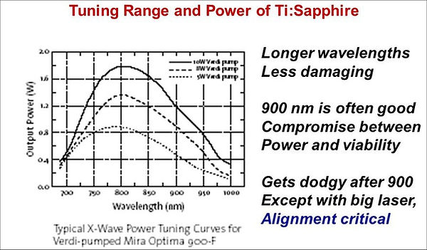
According to the slide reproduced below, 'the longer the Ti:S emission wavelength, the lower the damage', so whilst it may offer a higher power output, its longevity is suspect. However I'm puzzled why they are fixated on 900nm as a compromise when 808nm is a common and strong laser diode fundamental:
http://slideplayer.com/slide/8218028/33/images/30/Tuning+Range+and+Power+of+Ti:Sapphire.jpg
Ti:S can indeed be LD pumped, as can Alexandrite: [O3], Solid-State Lasers - A Graduate Text, page 85, says 'Alexandrite can operate both as a 4-level vibronic laser and as a 3-level system analogous to Ruby. As a 3-level laser it has a high threshold, fixed output wavelength of 680.4nm at room temperature [680nm + 266nm = 191.205nm and 680.4 = 191.237nm], and relatively low efficiency. The absorption peak near 680nm has been exploited using diode laser pumps.'
As for about my idea of Alexandrite at 750.4nm, yielding 196nm; Alexandrite absorption peaks are
420nm & 580nm, with my estimated ranges 370-470, 540-650nm based on the graph shown here:
Found here:
Nd:YAG characteristics & absorption graphs, my estimated peaks: 590, 740, 750, 793, 810, [807.5nm]
Nd:YAG characteristics & absorption graphs, my estimated range: 350-370, 450-600, 790-830, 869, 885nm:
http://www.northropgrumman.com/BusinessVentures/SYNOPTICS/Products/LaserCrystals/Pages/NdYAG.aspx
Nd:YLF characteristics & absorption graph, my estimated range: 780-815, 865nm:
http://www.northropgrumman.com/BusinessVentures/SYNOPTICS/Products/LaserCrystals/Pages/NdYLF.aspx
Nd:YLF absorption peaks: 750, 793, 798, 804nm:
http://www.alphalas.com/images/stories/products/laser_components/Laser_Crystals_ALPHALAS.pdf
Peaks: Emission Absorption (peak = |, range = ...) Absorption ranges
Nd:YAG 1064 ..............|590 ||750.|808.. 450-600, 790-830 etc
Nd:YLF 1047 .||.. || 780-815, 865
Ti:Sapphire 800 ......|495...... 440-600
Alexandrite 750 ....|420.. ....|580.... |680 370-470, 540-650
Ruby 694 .|400.. .....|554.. 380-450, 500-600
TmHoCR:YAG 2081 ......................................|781 400-800
Range:300 400 500 600 700 800 900 nm
+01234567890123456789012345678901234567890123456789012345678901 x 10nm
I also discovered TmHoCr:YAG lases at 2081nm, which could act as a substitute for the Nd:YAG-derived 2074nm in paper [O12]; after all, I did not have to go their route.
However even if these alternatives could produce sufficient power, I would still need a specialised summing crystal either for 700nm + 266nm, or 2081nm + 213nm. As before, I decided to acquire the different materials if they came up cheaply on eBay so I could experiment, but to concentrate on producing 213nm for the main project.
NLO CRYSTAL PARAMETERS
Unlike the researchers who wrote the 2003 paper [O12], I am unfamiliar with the optical, chemical and physical properties that define a NLO for its purpose, thus unable to specify the necessary parameters to order new crystals from manufacturers (NLOs are typically very expensive). Again, the only practical way forward was to buy surplus NLOs that had been used in similar applications. However the more I read about them, the more I realised I would have to be careful about my choice.
NLOs are manufactured from many compounds but a few kept cropping up, all having different properties, all having differing bandwidths, some better at high power, some more stable at temperature, most hygroscopic. BBO, KD*P, KTP and D*CDA are some of the more common:
The values below are taken from tables in [References: Optical Materials]
BBO = BaB2O4 = Beta Barium Borate
Range 190nm - 3300nm
BBO is moderately hygroscopic
BBO has a damage threshold of 10GW/cm² @ 1064nm 1.3ns 10Hz / 120MW/cm² 8ns 10Hz @ 266nm
D*CDA = CsH2AsO4 aka CD*A / DCDA Deuterated Cesium D-hydrogen Arsenate
Range 260nm - 1100nm
D*CDA is VERY hygroscopic
D*CDA has a damage threshold of 360MW/cm² (Quantum Tech. datasheet DS707)
KD*P= KD2PO4 aka DKDP = Deuterated Potassium Dideuterium Phosphate
Range 200nm - 1600nm
KD*P is moderately hygroscopic
KD*P xtals are susceptible to thermal shock
KD*P has a damage threshold of 6GW/cm² @ 1064nm 1.0ns 10Hz
KTP = KTiOPO4 = Potassium Titanyl Phosphate
Range 350nm - 2700nm
KTP is non-hygroscopic
KTP has a damage threshold of 2.4GW/cm² @ 1064nm 11ns 2Hz
LBO = LiB3O5 = Lithium Triborate
Range 550-2600nm (Type I)
LBO is moderately hygroscopic
LBO has a damage threshold of 19GW/cm² @ 1064nm 1.3ns 10Hz / 200MW/cm² @ 266nm 1.3ns 10Hz
The star '*' in D*CDA or KD*P means the crystal was grown in heavy water [N27], and is referred to as 'deuterated'. Deuteration replaces hydrogen atoms with deuterium atoms, which increases:
the IR optical range of the material;
the electro-optic constant Fω;
the non-linear susceptibility constant Dx.
A common way of countering hygroscopic issues is to immerse the xtal (also applies to pockels cell xtals) in a fluorocarbon liquid that meets the index matching characteristics of the operating wavelengths. The last paragraph in [N18], FastPulse NLO User's Guide, warns this liquid must first be filtered.
KTP is regularly used in small milliwatt laser pointers, but is prone to photochromic damage (called grey tracking) during high-power 1064nm second harmonic generation which tends to limit its use to low-power and mid-power systems. KTP is also used as an electro-optic modulator (e.g. Pockels Cell), optical waveguide material, and in directional couplers. KTP crystals need stable temperature to operate if they are pumped with 1064nm IR to output 532nm green). Its low damage threshold renders it unsuitable for my project.
KDP / D*KDP pockels types are prone to ringing ([N5], Inrad BBO pockels Cells) which becomes evident the longer the crystal is biased - read into this frequency of pulses - but this should not affect me as LIBS will not require many pulses. This also applies to pockels cell crystals.
The following webpage gives a good introduction to the main criteria for NLO selection, explained in a very handy table reproduced below, that associates laser beam properties with NLO characteristics:
[N15] http://www.redoptronics.com/nonlinear-crystal-principal.html
Parameter For NLO Crystal Selection
Laser Parameters Crystal Parameters
NLO Process Phase-Matching Type and Angle, deff
Power or Energy, Repetition Rate Damage Threshold
Divergence Acceptance Angle
Bandwidth Spectral Acceptance
Beam Size Crystal Size, Walk-Off Angle
Pulse Width Group Velocity Mismatching
Environment Temperature Acceptance, Moisture
The site goes on to explain Crystal Acceptance, Walk-off and Group Velocity Mismatch, the latter apparently of importance to super fast lasers and in this respect Ti-Sapphire is mentioned, but my interest is for low speed use (ns vs fs) so I assume I can ignore this for now.
TEMPERATURE TUNING
Often NLOs are contained within an assembly with a heating element and feedback temperature sensor. However BBO can also be cooled to advantage, therefore it is not safe to assume all HG assemblies with connectors for heaters/thermistors are likely to contain the same crystal type.
[G20] Deepseek question: Define NLO temperature and angle tuning:
[Deepseek] The phase-matching condition can be fine-tuned by adjusting the temperature of the crystal or the angle of incidence. This allows some flexibility in the input wavelengths, but the range is still limited. For example, angle tuning might allow a small shift in the input wavelengths (e.g., ±0.5nm to ±2nm), but this depends on the specific crystal and setup.
CRYSTAL ACCEPTANCE
[N15] 'If a laser light propagates in the direction with angle Dq to phase matching direction, the conversion efficiency will reduce dramatically (see the right Figure). We define the acceptance angle (Dq) as full angle at half maximum (FAHM), where q = 0 is phase-matching direction. For example, the acceptance angle of BBO for type I frequency doubling of Nd:YAG at 1064nm is about 1 mrad-cm. Therefore, if a Nd:YAG laser has beam divergence of 3 mrad for frequency-doubling, over half of the input power is useless. In this case, LBO may be better because of its larger acceptance angle, about 8 mrad-cm. For NCPM, the acceptance angle is normally much bigger than that for CPM, for example, 2 mrad-cm1/2 for Type I NCPM LBO. In addition, you have to consider the spectral acceptance (Dl) of the crystal and the spectral bandwidth of your laser; crystal temperature acceptance (DT) and the temperature change of environment.'
DIVERGENCE
[O1], Laser Safety Manual V4, from the university of Victoria, explains many laser parameters.
For instance, the section on beam divergence says: 'Although a laser beam is directional, some divergence (beam spread) does occur. This results in an increase in the beam diameter as the distance from the exit port of the laser increases. Beam divergence is measured in milliradians (17.45mrad = 1°) and lasers typically have a beam divergence of about 1mrad.'
[C18] provides links to online converters for mrad to degrees and vice versa.
The MK367 datasheet [O6] specifies divergence at 20% ~ 1.1mrad [0.06°] full angle', suggesting it would produce good power through BBO, but there is no mention of KT*P.
Deepseek question: what is the divergence of KT*P:
[Deepseek] The divergence of a laser beam, including one generated using a deuterated potassium titanyl phosphate (DKTP) nonlinear crystal, depends on several factors such as the laser cavity design, the quality of the crystal, and the beam waist. However, the divergence of the laser beam itself is not typically specified for the crystal alone but rather for the entire laser system. For a well-designed laser system using a DKTP crystal, the divergence can be quite low, often in the range of a few milliradians (mrad). For precise divergence values, you would need to consider the specific laser system and its design parameters.
a) Typical divergence:
1 to 5 mrad (milliradians) for many solid-state lasers using nonlinear crystals like DKTP.
b) High-quality systems:
Divergence can be as low as 0.5 to 1 mrad with optimized cavity design and beam shaping.
Divergence may or may not be an issue for the MK580. I can attempt to improve it using a beam expander/reducer, and I can verify it using an optical shearing interferometer, aka 'optical shear plate'. This is why when a cheap one came up on eBay I grabbed it, although the interchangeable plate it came with is designed for a larger beam and I'm still waiting for a smaller plate to appear. The part I got is a Thorlabs SI-254P designed for a 10mm to 25.4mm beam however it may still be useful when paired with an expander: http://www.thorlabs.com/newgrouppage9.cfm?objectgroup_id=2970
WALK-OFF ANGLE
[N15] 'Due to the birefringence of NLO crystals, the extraordinary wave (ne) will experience Poynting vector walk-off. If the beam size of input laser is small, the generated beam and input beam will be separated at a walk-off angle (r) in the crystal and it will cause low conversion efficiency. Therefore, for focused beam or intra-cavity doubling, the walk-off is a main limitation to high conversion efficiency.'
Alternative wording from [Deepseek]:
In birefringent crystals, the walk-off effect (spatial separation of the ordinary and extraordinary rays) can limit the effective interaction length. A smaller beam radius can help mitigate this effect by reducing the spatial separation.
From the above I read: the larger and shorter the crystal, the better. DeepSeek also reveals the benefit of a tight focus:
FOCUS
Multiple papers I read indicated NLO output power is dependent upon a tight focus but none gave examples. When I asked an independent researcher if I should focus the beam into an NLO I was rebuffed with a firm warning that I might exceed the damage threshold of the material.
Deepseek question: What is the optimum pump beam radius for a laser nonlinear crystal harmonic?
[Deepseek] The walk-off effect (spatial separation of the ordinary and extraordinary rays) can limit the effective interaction length. A smaller beam radius can help mitigate this effect by reducing the spatial separation.
3. Focusing and Confocal Parameter: The beam radius is related to the focusing of the pump beam. The confocal parameter (Rayleigh range) should be comparable to or longer than the crystal length to ensure efficient interaction. The optimal beam waist ω0 can be estimated using:
__
/λL
ω0 ≈ √ 2π
where λ is the wavelength of the pump beam and L is the length of the crystal.
4. Damage Threshold: The pump beam radius should be large enough to avoid exceeding the damage threshold of the crystal. High-intensity beams with small radii can cause optical damage.
5. Nonlinear Interaction Length: The effective nonlinear interaction length is influenced by the beam radius. A smaller beam radius increases the intensity, which can enhance nonlinear effects, but it also reduces the interaction length due to diffraction.
6. Empirical Optimization: Often, the optimum pump beam radius is determined empirically by varying the beam waist and measuring the harmonic output power. This experimental approach accounts for practical
factors such as crystal quality, alignment, and thermal effects.
Example Calculation
For a typical second-harmonic generation (SHG) process in a beta-barium borate (BBO) crystal with a pump wavelength of 1064nm and a crystal length of 10mm, the optimal beam waist might be around 20-50µm, depending on the specific conditions and desired efficiency.
Summary
The optimum pump beam radius is a trade-off between maximizing nonlinear interaction, maintaining phase matching, and avoiding damage. It is often determined through a combination of theoretical modeling and experimental optimization.
Addendum: above calculation checked & other wavelengths & lengths (see my NLOs listed below) added:
Example above My 2HG My 3HG My 4HG My 5HG
__ _____________ ____________ ____________ ___________ ___________
/λL /1064nm x 10mm /532nm x 30mm /355nm x 20mm /266nm x 6mm /213nm x 5mm
ω0 ≈ √ 2π √ 2π √ 2π √ 2π √ 2π √ 2π
Answer = 41.15µm = 63.03µm = 33.62µm = 15.94µm = 13.02µm
Next I need to determine material damage threshold, see [References: Optical Materials].
Deepseek question: Calculate the optimum pump beam radius for a laser nonlinear crystal harmonic. I expected little more than above, but much more came back:
[Deepseek] To calculate the optimum pump beam radius for a laser nonlinear crystal harmonic generation, you need to consider the trade-off between the nonlinear conversion efficiency and the damage threshold of the crystal. The goal is to maximize the conversion efficiency while avoiding damage to the crystal.
The optimum pump beam radius is determined by balancing the need for high intensity (small beam radius) to maximize nonlinear conversion efficiency against the need to avoid damaging the crystal (intensity below the damage threshold). The calculation involves determining the beam waist radius that allows the maximum power to be used without exceeding the crystal's damage threshold.
Key Parameters:
1. Nonlinear Conversion Efficiency
This depends on the intensity of the pump beam, which is inversely proportional to the beam area (i.e., smaller beam radius leads to higher intensity).
2. Damage Threshold
The crystal can only withstand a certain maximum intensity before it gets damaged. This limits how small the beam radius can be.
Steps to Calculate the Optimum Pump Beam Radius:
1. Determine the Damage Threshold Intensity (Imax):
a) This is typically provided by the crystal manufacturer or can be found in literature.
b) Imax is the maximum intensity (power per unit area) that the crystal can withstand without damage.
2. Calculate the Maximum Allowed Power (Pmax):
The maximum power that can be used without damaging the crystal is given by:
Pmax = Imax x π x ω0²
where ω0 is the beam waist radius (the radius at which the intensity drops to 1/e² of its peak value).
3. Relate Beam Waist to Beam Radius:
The beam waist ω0 is related to the beam radius ω(z) at any position z along the beam path by:
__________
ω(z) = ω0 /1 + ( z )²
√ ( zR )
where zR = π x ω0² is the Rayleigh range, and λ is the wavelength of the pump beam.
λ
4. Optimize for Conversion Efficiency:
a) The conversion efficiency η for harmonic generation is typically proportional to the intensity squared (for second harmonic generation, 2HG):
η ∝ I² ∝ ( P )²
( πω0² )
b) To maximize η, you want to maximize I, but you are constrained by Imax.
5. Set Intensity to Maximum Allowed:
a) To avoid damage, set the intensity I to Imax:
I = P = Imax
πω0²
b) Solving for ω0:
______
ω0 = / P
√ πImax
6. Consider Beam Propagation:
a) If the crystal is not at the beam waist, you need to account for the beam radius at the crystal position z:
__________
ω(z) = ω0 /1 + ( z )²
√ ( zR )
b). Ensure that the intensity at the crystal does not exceed Imax.
7. Iterate for optium radius:
You may need to iterate the calculation to find the optimum beam radius that maximizes conversion efficiency while keeping the intensity below the damage threshold.
Example Calculation:
Assume:
P = 1W (pump power)
Imax = 1GW/cm² = 1^11W/m² (damage threshold)
λ = 1064nm (pump wavelength) [why is this relevant here?]
Calculate w0:
______ ______________
ω0 = / P / 1W ≈ 5.64×10^−6m = 5.64µm
√ πImax √ π x 1^11W/m²
Deepseek question: Calculate beam waist radius that maximizes conversion efficiency without exceeding the damage threshold for 1064nm with pump power 1W and damage threshold 1GW/cm².
[Deepseek] To calculate the beam waist radius that maximizes conversion efficiency without exceeding the damage threshold, we need to ensure that the intensity of the beam does not surpass the damage threshold of the material. Here's how you can approach this problem:'
Given:
Wavelength, λ = 1064nm = 1064 × 10^-9m
Pump power, P = 1W
Damage threshold, Ith = 1GW/cm² = 1 × 10^9W/cm² = 1 × 1^12W/m²
1. Relate intensity to beam waist radius
a) The intensity I of a Gaussian beam is given by:
I = 2P
π x W0²
where P is power of the beam and W0 is the beam waist radius
2. To avoid damage, the intensity must satisfy: I ≤ Ith
a) Substitute the expression for I:
2P ≤ Ith
π x W0²
3. Solve for the beam waist radius W0
a) Re-arrange the inequality to solve for W0:
W0² ≥ 2P
π x Ith
_______
W0 ≥ / 2P
√ π x Ith
3. Plug the values:
______________
W0 ≥ / 2 x 1
√ π x 1 x 1^12
______________
W0 ≥ √6.366 x 1^-13
W0 ≥ 7.98 x 1^-7m
W0 ≥ 0.798µm
4. Interpret the result
a) The beam waist must be at least 0.798µm to ensure the intensity does not exceed the damage threshold of 1GW/cm²
b) To maximize conversion efficiency, you would typically operate close to this minimum beam waist radius, as smaller beam waists lead to higher intensities and better nonlinear interaction. However, you must ensure the beam waist does not become smaller than 0.798µm, as this would exceed the damage threshold.
c) The beam waist radius that maximizes conversion efficiency without exceeding the damage threshold is approximately 0.798µm.
This is a different answer specifically for a Gaussian TEMoo beam, but there was no mention of this in the previous answer, so I revised my question:
Calculate beam waist radius that maximizes conversion efficiency without exceeding the damage threshold for 1064nm with pump power 1W and damage threshold 1GW/cm².
This time it again came up with the answer of 5.64µm so at least that's consistent.
DeepSeek appears to be my solution for determine laser parameters for NLO experimentation.
PRACTICALITY
Another factor critical to me alone, is my ability to actually focus to this extreme. Given I now know what to aim for, purely from practicality I shall aim to focus the 1064nm to 100µm and If I can achieve better, 50µm.
Whatever the focus, I shall need a means of verifying it. see [References: Detectors & Visualisers].
OTHER CRITICAL FACTORS
This excellent site also provides invaluable cautionary information:
'In many cases, a nonlinear crystal used for nonlinear frequency conversion has a very long lifetime, which is longer than that of the whole laser system. The crystal material is essentially not modified during operation. However, a reduced crystal lifetime can occur under various circumstances:
Excessive optical intensities during operation may instantly damage a crystal. Unfortunately, nonlinear crystals often need to be operated not far from their optical damage threshold in order to achieve a sufficiently high conversion efficiency. This implies a trade-off between conversion efficiency and crystal lifetime. Note that even if the nominal intensity is below the nominal damage threshold, there may be problems due to fluctuations of the beam power or local intensity (e.g., if a beam profile has "hot spots"), or due to isolated defects in a crystal, which are more sensitive than the regular crystal material.
Even well below the threshold for instant damage, some crystal materials exhibit a continuous degradation within the used volume, e.g. in the form of "gray tracking". Such phenomena are particularly common for operation with ultraviolet light. Note that a gradual degradation can also lead into instant catastrophic damage via excessive heat generation.
Hygroscopic crystal materials deteriorate when they are not always kept in sufficiently dry air (or a dry purge gas). This applies e.g. to KDP and BBO, and in a lesser extent to LBO. It can be helpful to keep such a crystal at a somewhat elevated temperature, which makes it easier to keep it dry.
Operation of nonlinear crystals at temperatures below room temperature (in order to achieve phase matching) is generally problematic, as it may lead to condensation of water on the crystal surfaces if the surrounding air is not very dry. Even if the crystal material or coating is not sensitive to water, small water droplets may focus laser radiation more tightly than under normal operation, and thus damage the crystal material.
Crystals which are non-critically phase-matched in a crystal oven may exhibit problems when the crystal temperature is changed too rapidly or too often. In particular, anti-reflection coatings may be damaged due to different thermal expansion coefficients of the involved materials.
Crystal lifetime can also be strongly dependent on the material quality, although certain degradation phenomena appear to be intrinsic limitations of the material.
For high-power UV generation, nonlinear crystals may become consumables: they need to be replaced quite often within the lifetime of the whole laser system (e.g., every few hundred hours of operation). Often, several problematic aspects come together in the regime UV generation: crystal materials are generally more sensitive to ultraviolet light (having high photon energies), exhibit a higher absorption in that regime, and in case of ultrashort pulses the high group velocity mismatch enforces the use of a shorter crystal, which requires high optical intensities for a given conversion efficiency.'
Hot spots are also an issue with NLOs, as described here:
[N15], Principles of Nonlinear Optical Crystals - Conversion Efficiency, Red Optronics website: 'Note that even if the nominal intensity is below the nominal damage threshold, there may be problems due to fluctuations of the beam power or local intensity (e.g., if a beam profile has "hot spots"), or due to isolated defects in a crystal, which are more sensitive than the regular crystal material.'
ADD PAPER THAT SAYS COOLING BBO EXTENDS ITS LIFE
It was clear I would need to use crystals with a certain pedigree to stand any chance of harmonic generation, and as I read up about them, I realised most were composed of hygroscopic salt compounds, therefore unsealed, raw crystals were to be avoided. I also learned crystals were most efficient at certain temperatures dependent on their chemical composition, but are susceptible to thermal shock and could be destroyed by fluctuations sharper than 1°C per minute. I found hygroscopic ones were best operated in indexing fluid, which was typically FC-43 fluorocarbon, usually with a bubble for thermal expansion.
Eventually I realised my best choice was large, used crystal assemblies from laser companies Continuum and Quantel. These consist of large plastic cubes with metal guides inside on which the NLO is already installed. On eBay over time, I was able to acquire the following Nd:YAG harmonic converters.

NLO harmonic crystals:
Left 2HG
1064nm->532nm
Right 3HG
1064nm + 532nm->355nm


NLO harmonic crystals:
Left 4HG
532nm->266nm
Right 5HG
355nm + 532nm->213nm

BARE CRYSTALS
Unfortunately my assemblies are for OEM lasers and their labels give little away, the T suggesting temperature tuning, the number either crystal length or in the case of the 5th harmonic, the requisite 2nd and 3rd harmonic inputs. The biggest problems are working out what they are made of which determines the desired operating temperature, the required phase of the input wavelength, and the angle at which they produce the highest output:
Dimensions Phaseφ Angleθ Type App Input Output Manf Part No. Heater Chem
11x11x30 45°? 37.7°? I? 2HG 1064nm 532nm Continuum SHG-T-30 YES KD*P?
12x12x20 90°? 59.3°? II? 3HG FND + 2HG 355nm Continuum THG-T-2 NO KD*P?
6x6x6 90°? 47.6°? I? 4HG 532nm 266nm Continuum FHG-T- NO BBO?
7x7x5 90°? ? I? 5HG 2HG + 3HG 213nm Quantel 5HG-3+2 NO BBO?
My '?' guesses above are based on the chance of the crystals being the same as those listed below, from http://laser-sources.co.uk/Harmonic-Crystals.php
http://www.crylight.com/product/detail.jsp?myid=215854
Inrad Optics brochure listing standard KD*P xtals:
https://www.inradoptics.com/pdfs/KDP_KD*P_DataSheet.pdf
Chrysmit has a huge table of BBO xtals with parameters:
http://www.crysmit.com/BBO-stock.html
Eksma has a large table with parameters:
https://eksmaoptics.com/nd-yag-laser-line-components/nd-yag-laser-line-crystals/harmonics-crystals/
Phase is the orientation of the crystal to the laser beam, adjustment being by mechanical rotation or optically using a polariser, several of which I acquired.
Lacking the ability to determine crystal parameters by calculation, I wondered if it was possible to guess their function knowing Type, Phase φ and Angle θ. I created the list below from crystals I found on their manufacturers' sites and eBay.
Laser Sources UK identifies TYPE I and TYPE II that specify the required orientation of the incoming beam, with TYPE I often being 45.0° and TYPE II 90.0° although BBO and LBO differ; BBO entries from crylight.com associate TYPE I with 0°.
Note 1: Castech = Fujian Castech Crystals Inc.
Note 2: Phase = φ (Phi), Angle = θ (Theta)
Note 3: Type is listed under 'Phase Match'
Note 4: HG below is generally but not always derived from the Nd:YAG 1064nm fundamental
KTP
KTP Laser Sources UK
Dimensions Phaseφ Angleθ Type App Input Output
3x3x5mm 90° 23.5° II 2HG 1064nm 532nm
6x6x8mm 90° 23.5° II 2HG 1064nm 532nm
3x3x10mm 90° 23.5° II 2HG 1064nm 532nm
'White KTP' Castech (eBay)
Dimensions Phaseφ Angleθ Type App Input Output #
6x6x20mm 0° 69.1° ? ? 532nm 915.5nm F9860-1
Google AI: '"White KTP" (Potassium Titanyl Phosphate) laser crystals are often distinguished from standard KTP to highlight that they are higher-quality, hydrothermal-grown crystals, which appear clearer or "whiter" than the more common, cheaper flux-grown KTP crystals; they are used for high-power laser applications and in industrial, medical, or military, whereas lower-quality flux KTP is often limited to low-power applications like green laser pointers.'
KDP
KDP Laser Sources UK
Dimensions Phaseφ Angleθ Type App Input Output
13x13x20mm 45° 78.0° I 4HG 532nm 266nm
16x16x20mm 45° 78.0° I 4HG 532nm 266nm
12x12x20mm 45° 78.0° I 4HG 532nm 266nm
12x12x20mm 45° 83.0° I 2HG
KD*P (DKDP)
KD*P (DKDP) Laser Sources UK
Dimensions Phaseφ Angleθ Type App Input Output
12x12x40mm 45° 37.7° I 2HG 1064nm 532nm
13x13x40mm 45° 37.7° I 2HG 1064nm 532nm
16x16x40mm 45° 37.7° I 2HG 1064nm 532nm
12x12x33mm 90° 53.4° II 2HG 1064nm 532nm
16x16x23mm 90° 53.4° II 2HG 1064nm 532nm
12x12x45mm 90° 53.4° II 2HG 1064nm 532nm
13x13x45mm 90° 53.4° II 2HG 1064nm 532nm
16x16x45mm 90° 53.4° II 2HG 1064nm 532nm
12x12x30mm 90° 56.3° II Doubler/Mixer
13x13x33mm 90° 59.3° II 3HG 355nm
12x12x42mm 90° 59.3° II 3HG 355nm
16x16x33mm 90° 59.3° II 3HG 355nm
12x12x20mm 45° 63.0° I 2HG
10x10x20mm 45° 74.0° I 2HG 270-290nm
12x12x20mm 45° 74.0° I 2HG 270-290nm
12x12x20mm 45° 78.0° I 2HG 225-240nm
KD*P (DKDP) Castech (eBay)
Dimensions Phaseφ Angleθ Type App Input Output #
13.5²x20mm 90° 59.5° II? 3HG 355nm G6752-2
BBO
Below left Castech BBO tuning curves Below right - add Inrad's table they sent to me
and/or add Inrad's type definitions from brochure below

BBO Inrad
Dimensions Phaseφ Angleθ Type App Input Output #
12x12x1mm 90° 29.2° ? 2HG? 400-800nm 400-800nm BBO-1204H
BBO Laser Sources UK: HG
Dimensions Phaseφ Angleθ Type App Input Output
8x8x2.5mm 90° 47.6° I 4HG 532nm 266nm (Type may be wrong?)
6x6x7mm 0° 73.9° I? 3HG 608nm 203nm
BBO Castech
Dimensions Phaseφ Angleθ Type App Input Output #H7739-5
8x8x10mm 90° 49.2° ? ? 263nm 211nm
BBO Crylight.com: HG
Dimensions Phaseφ Angleθ Type App Input Output
4x4x7mm 0° 22.8° I 2HG 1064nm 532nm
4x4x7mm 0° 31.3° I 3HG 1064nm 355nm
4x4x7mm 30° 38.6° II 3HG 1064nm 355nm
4x4x7mm 0° 47.6° I 4HG 1064nm 266nm
4x4x7mm 0° 51.1° I 5HG 1064nm 213nm
BBO Crylight.com: OPO and OPA pumped by harmonics of Nd:YAG lasers
Dimensions Phaseφ Angleθ Type App Input Output
8x6x12mm 0° 21° I OPO 532nm Pump 680-2600nm
8x6x12mm 0° 30° I OPO 355nm Pump 410-2600nm
8x6x12mm 30° 37° II OPO 355nm Pump 410-2600nm
8x6x12mm 0° 39° I OPO 266nm Pump 295-2600nm
BBO Castech: OPO and OPA pumped by harmonics of Nd:YAG lasers
Dimensions Phaseφ Angleθ Type App Input Output #
8x5.5x14mm 0° 38° ? OPA 355nm Pump 420-2300nm G0594-1
12x8x14mm 0° 36.7° II ? 355nm 355nm M2393-1
BBO Crylight.com: Frequency doubling of dye lasers
Dimensions Phaseφ Angleθ Type App Input Output
8x4x7mm 0° 40° I 2HG 670-530nm 335-260nm
8x4x7mm 0° 55° I 2HG 600-440nm 300-220nm
8x4x7mm 0° 80° I 2HG 444-410nm 222-205nm
BBO Crylight.com: Harmonic generations of Ti:Sapphire lasers
Dimensions Phaseφ Angleθ Type App Input Output
5x5x0.2mm 0° 28° I 2HG 700-1000nm 350-500nm
5x5x0.2mm 0° 42° I 3HG 700-1000nm 240-330nm
5x5x0.2mm 0° 66° I 4HG 700-1000nm 210-240nm
BBO Crylight.com: Frequency doubling and tripling of alexandrite lasers
Dimensions Phaseφ Angleθ Type App Input Output
6x4x7mm 0° 31° I 2HG 720-800nm 360-400nm
6x4x7mm 0° 48° I 3HG 720-800nm 240-265nm
BBO Castech: crystal plate (eBay)
Dimensions Phaseφ Angleθ Type App Input Output #
5x5x0.5mm 0° 36° I? 2HG 550-800nm 275-400nm F0831-5
5x5x1.0mm 0° 20° I? 2HG 1150-1600nm 575-800nm F0831-3
5x5x1.0mm 0° 21° I? 2HG 1600-2300nm 800-1150nm CK0274
BBO Claser Inc: crystal plate (eBay)
Dimensions Phaseφ Angleθ Type App Input Output
10x8x0.5mm 0° 29° I? N/S 360-2700nm 360-2700nm
BBO Crylight.com: Intracavity SHG of Ar+ laser with brewster angle cut BBO Crystal
Dimensions Phaseφ Angleθ Type App Input Output
4x4x7mm 0° 51° I 2HG 514nm 257nm
4x4x7mm 0° 55° I 2HG 488nm 244nm
LBO
LBO Cristal Laser France SA (eBay)
Dimensions Phaseφ Angleθ Type App Input Output
2x2x5mm 10.7° 90° ? 2HG 1064nm 532nm
LBO Castech (eBay)
Dimensions Phaseφ Angleθ Type App Input Output #
3x3x10mm 8° 90° ? 2HG 1064nm 532nm F9825-1
2x2x5.3mm 16.6° 90° I *** ? ? J1305-1 ***See Google AI Note 2
LBO Laser Sources UK
Dimensions Phaseφ Angleθ Type App Input Output
6x6x12mm 11.6° 90° I 2HG 1064nm 532nm
5x5x15mm 90° 42.7° II 3HG 1064nm + 532nm 355nm
LBO Castech (eBay)
Dimensions Phaseφ Angleθ Type App Input Output #
7x7x18mm 90° 21.3° II 2HG 1064nm 532nm
7x7x18mm 90° 21.4° II 2HG 1064nm 532nm
7x7x18mm 90° 42.7° II 3HG 1064nm + 532nm 355nm
3x3x15mm 90° 43.3° ? 3HG 1064nm + 532nm 355nm G9706-3
7x7x18mm 90° 43.4° II 3HG 1064nm + 532nm 355nm
5x5x8mm 90° 43.3° ? 3HG 1064nm + 532nm 355nm G0391-1
4x4x7mm 90° 43.4° ? 3HG 1064nm + 532nm 355nm F5742-5
Google AI Notes:
1. 'LBO Key Advantage: Non-critical Phase-Matching (NCPM) removes spatial walk-off, allowing for longer crystals and higher efficiency.'
2. 'Type I is typically 11.6° to 17.6° and phi φ for LBO NCPM at 1064nm [for 2HG] is frequently cited as 11.6° in many catalogs, but values near 16.6° to 17.6° are also utilized in specific OPO/SHG configurations, often depending on the temperature, as LBO is temperature-tuned for best performance.'
LBO Castech (eBay)
3x3x3mm 0° 45.0° - - Castech part no. H2647-1
Customer comment: 'This is definitely not NLO crystal! Most likely a broadband polarizer and mode selector for multi-line lasers. LBO is negative biaxial birefringent crystal. The way it's cut is to maximize the spatial beam separations of orthogonal polarizations of the incident light. Placing of such crystal configuration inside laser cavity allows more stable multi-line laser generation from a single active media crystal as well as simple and effective mode selection.'
MORE RESOURCES
INRAD gives phase φ & angle θ vs nm info in its datasheet [N4] for its range of single crystal BBO NLOs.
'The phase matching angle for Nd:YAG laser system at maximum deff under room temperature is as following: theta=0° and phi=11.4° for Type I, theta=90° and phi=69.1° for Type II.':
http://www.unitedcrystals.com/LBOProp.html
This has a big LBO table with angle vs nm, including angle and phase:
http://www.newlightphotonics.com/Nonlinear-Optical-Crystals/LBO-Crystals
This has a big BBO table with angle vs nm, but angle and phase are missing:
http://www.newlightphotonics.com/Nonlinear-Optical-Crystals/BBO-Crystals
Eventually I realised I might never know what my crystals were, and I should instead proceed regardless, taking precautions with temperature rise. I found a manual for the Continuum Surelite laser [I25] which suggested its crystal heaters ran off 24 volts, so that was a start. Even if the crystals I had were from a completely different model, it seemed reasonably likely they would keep the same heater voltage.
Given the Nd:YAG lasers are pulsed, I bought a 2W CW 1064nm diode laser to check out all of the NLOs, starting with the small 2HG 1064nm -> 532nm crystal that came as a gift with the MK580 Nd:YAG. I
acquired a Wavelength Electronics WLD3343 2.2A driver hybrid IC, and made my own TEC-cooled assembly.
It lased, but blew after about an hour, possibly due to static damage or overheating, as my DIY TEC driver feedback loop was problematic. However I could not get it to produce 532nm from the small KTP crystal regardless of its orientation, perhaps due to poor polarisation. At this time I had no means of setting or observing the laser polarisation.
As a final effort but not expecting to see anything due to the single very short 4ns optical pulse, I tried the big 2HG assembly in the MK367 tray and on the second orientation effort, was amazed the Stellarnet confirmed 532nm clearly being generated, but I could not get the Panasonic DMC-FT5 colour camera I use for lab photos and videos, to record the green pulse. The spectrometer confirmed the intensity of the 532nm was about 59% that of the 1064nm, a very acceptable result, lab temperature 26.5°C. (AU = Arbitrary Unit of spectrograph vertical scale):
Below left, MK367 1064nm peaking at 62239 AU Below right: 2HG 532nm peaking at 36689 AU


Above, view taken from inside the MK367 drawer of the prototype rack, looking towards the drawer front. This orientation of the Continuum SHG-T-30 NLO produced 532nm from the 1064nm fundamental of the MK367 Nd:YAG, to its right. On the far left of the photo is the wooden block I use as a target, as it produces a diffused beam whose reflections I capture on the spectrometer. The black mark is a burn left from repeated firing of the laser.
REPEAT THIS AND MEASURE OUTPUT TOO:
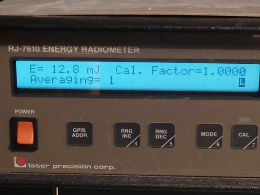
I measured the output from just the MK367 on a Laser Precision Rj-7610 energy radiometer with an
RJp-735, 1J probe and got a reading of 12.8mJ, so the 532nm would be around 6mJ. Part of the 12.8mJ
will be the optical energy from the MK367 flashlamp, evident in the MK367 spectrograph at the bottom of the dedicated section on the prototype. This is not present on the spectrographs above because they are from reflections on the wood after the 2HG converter.
The MK367 should produce 25mJ so I imagine this one (#1) is an old unit with many hours use.
Below left, the prototype rack, Below right, MK367 #1 produces 12.8mJ
ADD MK367 #2 7610 reading
ADD MK367 #3 7610 reading

After confirming the presence of 532nm I discovered the red AR coating on the 2HG window (below left photo) was damaged. This was the end I fired the MK367 into and only now did I realise I may have damaged it by incorrectly firing the MK367 1064nm into the wrong end of the NLO. The shape of the damage is smaller than the 3mm beam diameter of the MK367 [O6] but that is low order Gaussian [O54: P.476]. The red AR is only visible at a particular angle but I don't remember seeing damage before: normally the window is transparent, see below centre photograph where this damage is barely visible at the bottom left. I think it unlikely a 1064nm beam would damage the 532nm AR without also damaging its own AR although I would expect to be rated higher for the fundamental input. Given this 2HG came out of a 1GW laser it never occurred to me it would be damaged by a MK367 with a 6MW 25mJ pulse. It isn't too much of an issue as I have spares, but I should have run the AR coatings past the Stellarnet first: gold colour AR is 1064nm and red AR is 532nm (see my test results further down).
Furthermore on closer inspection I noticed the 2HG crystal ends are pitted with tiny holes (see photo below centre left), but that was definitely from its past life; the MK367 beam wasn't focused, so this damage was not due to me. Best crystal efficiency is achieved at high power density which can pit the crystal surface over time. Since crystals are expensive to replace, one workaround is to nudge the crystal or laser every 100 hours so the beam can strike a new, undamaged area. In a digitally controlled system this is recognisable by an orderly matrix of pits (centre right: an LBO crystal with a clear pit matrix from a 355nm beam). In my case the pits seem more random but discounting duplicated pits on the opposing side, multiple horizontally spaced rows can be made out so this seems the most likely explanation. It would also explain how it ended up on eBay, myself being ignorant of this when I bought it. However the 2HG seemed to work fine, probably because the pits are far smaller than the 3mm MK367 beam diameter. Not having an identical pristine 2HG crystal, I have no means of determining any detrimental effect, although I have no way of knowing for certain what the NLO material is anyway (ironic given this is for an experimental LIBS system and DUV is best for transparent materials, although I doubt that can be argued for a physically soft salt crystal).
An established practice is to employ fluorocarbon (FC) as an indexing fluid between the crystal and the windows, I assume to minimise energy otherwise lost in the refractive transition to air and back.
[N18] FastPulse (Lasermetrics) states:'Most standard production...Q-switches utilize type 43 fluid... Type 43 fluid has a slightly better index match than [41].' The label on my Inrad N530C 1064nm pockels Q-switch says 'FC43', so I assume these numbers refer to FC-41, FC-43.
I have some reclaimed, filtered, FC-77, see [Cooling Loop]. If I immerse the crystal in my FC liquid it should act as a heatsink.
Deepseek question: Will this reduce or remove the likelihood of pitting?
[Deepseek] Yes, immersing a nonlinear crystal like deuterated potassium dihydrogen phosphate (DKDP) in a fluid such as FC-74 can help reduce heat buildup and potentially mitigate pitting caused by a focused laser beam during harmonic generation. Here's how:
1. Heat Buildup Reduction:
Thermal Conductivity: FC-74 can act as a heat sink, drawing heat away from the crystal. This helps dissipate the heat generated by the intense laser beam, reducing thermal gradients and stress within the crystal.
Temperature Stability: The fluid can help maintain a more uniform temperature distribution across the crystal, minimizing thermal lensing effects that can degrade beam quality and harmonic generation efficiency.
2. Reduction of Pitting:
Laser-Induced Damage Threshold (LIDT): Pitting is often caused by localized heating and subsequent material breakdown at the laser focus. By dissipating heat more effectively, FC-74 can reduce the peak temperature at the focal spot, potentially increasing the LIDT and reducing the likelihood of pitting.
Surface Protection: The fluid can also act as a protective layer, reducing direct exposure of the crystal surface to the laser beam and mitigating damage from contaminants or imperfections on the surface.'
FastPulse states O-ring rubber seals must be made of Viton for FC; 3M revealed to me FC decomposes neoprene. It is likely but by no means certain the O-ring seals in my Quantum / Continuum HG assemblies are Viton, but they are OEM modules without specifications; it may be prudent to replace them with Viton O-rings before adding FC.
Question 2: Can I use FC-77 in place of FC-43?
https://multimedia.3m.com/mws/media/64889O/3m-novec-fluorinert-electronic-liquid-fc43.pdf
https://detector-cooling.web.cern.ch/data/3M_Fluorinert.pdf
http://www.quantumtech.com/PDF/707.PDF
http://www.fastpulse.com/pdf/eomgenl.pdf
If FC-43 is better than FC-41, comparing their RI values [D38] should indicate the best direction to follow. Unfortunately I can find no Technical Data Sheet (TDS) for FC-41. However Fastpulse also says:
'Another fluid in use is Decalin. Its refractive index is an almost perfect match for KDP type crystals and fused silica windows. Unfortunately it is extremely odorous, unpleasant to work with and is thought to be carcinogenic. Decalin fluid requires special filter elements and assemblies because it will chemically attack many plastics.'. Wikipedia gives its RI: https://en.wikipedia.org/wiki/Decalin
Deepseek question: What is the RI of the following FC variants:
[Deepseek] Refractive index at 589nm (Sodium D-line) at room temperature (around 20°C or 68°F):
FC-41 RI = 1.28
FC-43 RI = 1.29
FC-77 RI = 1.276
Decalin RI = 1.481
From this it is evident the RI for FC-77 is heading the wrong side of ideal, but it's only 0.01 worse than FC-43, therefore FC-77 would appear suitable for use as an NLO indexing fluid.
FastPulse says FC needs to be filtered - see last paragraph of [N18]. 'A 0.22 micron Millipore filter attachment or equivalent is recommended.' However FC degrades soft plastics that have by their nature been softened using plasticisers, see [Cooling Loop]. Nylon is one of these, and standard filters are typically made of nylon, e.g. Nylon Membrane Filter Pore Size 0.20µm Millipore GNWP00146,
3M P014601020NUC.
I suspect my FC container is made of polypropylene, and that may be the correct filter material to use.
Deepseek question: Is polypropylene affected by FC?:
[Deepseek] FC-74, aka perfluorohexane (C6F14) is not typically aggressive toward polypropylene under normal conditions. However prolonged exposure to FC-74 or elevated temperatures could potentially cause some swelling or minor degradation of it over time as fluorinated solvents can interact with polymers.
Further research:
Question 1: FC decomposes soft plastics. Will it also attack HG module heaters & wiring insulation?
This is probably the killer as there is no way of determining internal oven material types.
Question 2: What filter size was used to reclaim FC-74 to my PFX-90? Do I need to filter it better?


The success of producing 532nm encouraged me to add the 4HG NLO to the output of the 2HG but I could not get 266nm regardless of the rotation angle of the 4HG assy. It is possible there is a phase mismatch and it needs a waveplate. The 2HG label 'SHG-T-30' suggests it is temperature tuned, perhaps I was just lucky the 2HG worked at 26.5°C; the 4HG has no label, maybe it only works at an elevated temperature?
Afterwards I noticed a greyish mark on the entrance to the 4HG NLO that I did not recall seeing before (top right photo). At first I wondered if this might be the infamous grey tracking associated with excessive beam power, but I have never seen a photo of it. 'Tracking' implies crack-like darkened lines; although largely confined to the centre, it may instead be fogging due to hygroscopic ingress, a far worse issue since tracking damage can be reversed but fogging cannot: [N14] concludes grey tracking is due to excessive power levels, but on the last page (2403) it also says it can be reversed: http://nlo.stanford.edu/fejerpubs/1994/72.pdf
I have always kept all NLOs in sealed bags with desiccant in the warmest driest place of my house and the absence of fogging on other crystals suggests this is not a new issue, but instead another I failed to spot at purchase. As with pitting, there is a reason why expensive NLOs appear on eBay: many may be due to equipment decommissioning but I suspect most are swap-outs that have reached a level of damage warranting their replacement.
Better late than never, I confirmed the 2HG NLO AR coatings with the Stellarnet. By reflecting the 100W tungsten ceiling bulb off its end windows, I was able to confirm the gold AR is indeed the 1064nm input (the plot dips to zero reflection above 943nm), and the red AR is the 532nm output (the plot dips to zero reflection from 507nm to 545nm and above 943nm because both 532nm & 1064nm appear at the output.
Deepseek (2025):
'The color of an Anti-Reflective (AR) coating often corresponds to the wavelength of light it is designed to optimize. Here's a general guide:
Gold AR coating: Typically 1064nm (passes infrared).
Green AR coating: Likely 620-750nm (reflects green light, allowing complementary magenta / red to pass)
Red AR coating: Typically 500-550nm (reflects red light, allowing complementary green to pass)
Blue AR coating: Likely 450-500nm (reflects blue light, allowing complementary yellow / orange to pass)
For Deep Ultraviolet (DUV) wavelengths in the range of 190nm to 266nm, the Anti-Reflective (AR) coating color is typically not associated with a visible color like red, blue, or green. This is because DUV wavelengths are far outside the visible spectrum (which ranges from approximately 380nm to 750nm). Instead, AR coatings for DUV are designed to minimize reflection and maximize transmission at these specific wavelengths, and they often appear clear or slightly tinted to the human eye.
If we were to associate a color based on the coating's appearance under visible light, it might have a very faint purple or violet hue, as these are the shortest wavelengths in the visible spectrum and are closest to the DUV range. However this is more of an aesthetic association rather than a functional one. In practice, the coating's performance at DUV wavelengths is determined by its material composition and layer thickness, not its visible color. Materials like fluorides (e.g., MgF₂) and specialized oxides are commonly used for DUV AR coatings due to their low absorption and high transparency in this range.'
Given their expense, it's probably not a bad thing I'm experimenting with bad crystals. I've read they need to be run at a high enough power to achieve efficient conversion, but too much power will destroy them. I'm flying blind when it comes to this and it will take a fair amount of experimentation for me to determine where the safe limits are. For me this means running them at the highest power before pitting occurs. When I know that, I'll think about replacing them with pristine crystals. For now, I have a complete set of modules to support and protect the crystals whilst I experiment.
Below left the plots compared Below right, the correctly labelled 2HG
Reference plot,
tungsten lamp:
Red AR dips at
507nm - 545nm
& after 943nm
(532nm marker)
Gold AR dips after 943nm
(1064nm marker)


Temperature affects NLO HG operation, and some of the assemblies have electrical connectors carrying pairs of wires for both a heater coil and what could be a platinum PT1000 RTD (Resistance Temperature Detector) element. I was able to measure the resistance of both but not knowing the thermal characteristics, one plan is to place the unit in a thermal chamber and measure the RTD value wrt chamber temperature to calibrate the RTD, before applying power to the heater which I will also eventually have to control. At some point I'll construct a small chamber capable of going up to 150°C with precision timed ramp and fall.
ADD 9D PINOUT & MEASURED HEATER, RTD RESISTANCES
It is problematic using a single pulse Nd:YAG to verify NLO functionality. Because of this, I decided
to continue basic NLO experimentation with the 2W CW diodes I bought for this purpose, that I had abandoned after losing the first one to either ESD or overheating. Before resuming this approach I first acquired TEC and LD drivers and Lasorb LD ESD protectors, a new ESD mat for my lab bench, (basic safety) anti-static shoes and an ESD lab coat:
Wavelength LFI-3751 ±5A 40W TEC driver instrument [I18]
Wavelength LFI-4532 3.22A laser diode driver instrument [I19]
Pangolin LASORB L44-47-122-208-X [D4]
Multicomp 082-0028F ESD mat [D5], 600x1200mm, bottom layer 10^3Ω to 10^6Ω, top layer 10^6Ω to 10^9Ω
ESL-TH96-W 2/3 lab coat, 96% cotton, 4% ESD carbon loaded yarn 5mm grid, 10^6Ω to 10^7Ω, discharge <2s
https://www.somersetworkwear.com/esd-white-lab-coats
The NLO HG crystals above are specified for phase matching angle φ and tuning angle θ.
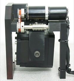
That leaves the tuning angle. In addition to the 2HG, 4HG assemblies listed above, I purchased two similar but cheap assemblies with broken crystals, that came with motors to adjust their angle for maximum efficiency. I plan to use the broken crystals for practice with the MK580 and later move the motors onto the good HG assemblies. Lacking a controller, I decided to design my own drivers, using Microchip PIC microcontrollers.
I also need to determine beam polarisation, critical for NLO operation. [Projects: Laser Polarimeter]
is an LHC offshoot to investigate the viability of dynamic polarisation feedback for NLO tuning.
Having confirmed from the MK367 the rotational position for phase matching of the 2HG crystal, I can at
least compare it with the output of the MK580 to determine confirm its polarity after Q-switching.
About this time, the project electronics system design began to emerge.
Below, the tuning angle motorised NLO assemblies. Wires are to motors and travel limit microswitches.
Left: SHG Right: THG


Below: Below:
Fractured 2HG crystal Fractured 3HG crystal


QUANTA RAY HG BLOCK ADD PHOTO
In 2022 I found a Quanta Ray four-crystal NLO block together with its NLO temperature controller (TC), with a plate indicating the presence of 2HG types I & II as well as 3HG and 4HG. Examining the manual I found online, I found the levers were set to disable all NLOs, the position I would expect it be be in if they had been removed, which I suspected was very likely, i.e. an empty box. I also discovered it was necessary to hook it up to a live N (Nitrogen) feed to counter NLO hygroscopic ingress. The N inlet and outlet were open so even if there were any NLOs inside they would likely be fogged.
I was however very interested in the TC to measure the temperature it was set up for and the range offered, and the seller accepted my offer of $100. After it arrived I peered through the glass apertures and was surprised to find the crystals not only all present but still looking transparent. I hooked up a glass bottle with indicating desiccant routed to the N inlet, sealed the outlet and placed it in my house airing cupboard where I keep all of my NLOs as humidity never rises above 35%.
I repaired a duff channel on the temperature controller and checked it worked. Originally I was going to open the box to directly measure temperature, but I found a connector inside the TC box, and measured the thermistor resistance which makes me assume it has PT100 elements that I can replicate and thus test the TC separately, TBD.
This is a major find, because together with its controller, it removes the headache of meeting the temperature, angle, phase, etc requirement to match successive NLOs to achieve DUV.
I will still use the separate HGs in experiments, but the final layout can now be much compacted, and may even all fit on the £300 600mm x 900mm research grade optical breadboard I found next!
New text box
New text box
⌠ ⌡ ∫ │ ─ √ φ θ Θ ∂ δ ζ ξ ς λ ψ ω τ µ Ω ∆ Δ ∑ ∏ π ∞ ∝ Ξ ○ ≠ ³ ² ± ≤ ∴