12. Optical Instruments
INSTRUMENT REPAIRS & MODIFICATIONS (IN ALPHANUMERIC ORDER)
# Action Status Problem Manufacturer Model Function
1 Refurb TBD Lethal Jinan Mao An JH-B Hollow Cathode Lamp Activator
2 Refurb Fixed Dim backlight Laser Precision Rk-5710 Power Radiometer 0 - 30W
3 Refurb Fixed Dim backlight Laser Precision Rj-7610 1-ch Energy Radiometer 0 - 1J
4 Refurb Fixed Dim backlight Laser Precision Rj-7620 2-ch Energy Radiometer 0 - 1J
5 Repair Fixed Not working Laser Precision RkP-575/Rk-570C Shutter motor control section
6 Repair Fixed Broken switch Oriel 68806 PSU Arc lamp PSU
7 Refurb Fixed Bad design Oriel Q Series case Arc lamp holder
8 Repair Fixed Broken lamp Newport 6251NS 75W Xenon arc lamp
9 Repair Ongoing Inaccurate Sequoia Turner 340 Spectrophotometer
10 Repair Ongoing Bad IR source Generic 360 FTIR chemistry analyser [TBD]
1. Jinan Mao An JH-B Hollow Cathode Lamp Activator (Rejuvinator)
INITIAL INSPECTION 10/03/14 LIBS3 P.10
This Chinese instrument rejuvenates hollow cathode tubes by using an established method of running a high voltage across them at a controlled current for a specific period of time.
Unfortunately it has been built to an atrocious standard that renders it lethal, and it needs a rebuild. It is in a plastic box but it has metal end plates. There is no transformer; it runs directly off the mains and no metalwork is earthed. Look at the soldering on the uninsulated mains neon!
The holes in the metal back are 6mm diameter - big enough to get a fairly large screwdriver through.
The BU208A HV transistor is insulated by a mica sheet from its aluminium plate in the bottom of the plastic box. The wire soldered to its case tag with a big amateur blob is hidden by a loose section of heatshrink that hasn't been shrunk. This wire's insulation outside diameter is 1.2mm, and the other end of it is soldered to the centre pin of the POS/NEG DPCO switch without any insulation covering it.
I measured 700V across the HCL and this is directly connected to the pos/neg switch which just swaps polarities so the HCL gets +-700V or -+700V; the uninsulated 1.2mm wire is carrying 700V. The small 'PE Lamp Socket' on the rear panel has exposed contacts that also carry 700V. Terrifying!
CHANGE THE CHASSIS UNDERSIDE PHOTO/DESCRIPTION - THE BU208A IS INSULATED BY MICA SHEET
Front panel HCL socket on top Rear no earth & big holes Instructions Limits


Metalwork not earthed Insecure components Mains neon no insulation HV resistors not secured


Internal metal is live! Self taps hold pcb! BU208A poorly insulated Bad insulation


HCL lamp Reverse-engineered cct NB 22k pot is 2W (for redesign)


Laser Precision optical power/energy meters - replaced all dimly lit LCD backlights (2022)
2. Laser Precision Rk-5710 Power Radiometer up to 30W
3. Laser Precision Rj-7610 Single Energy Radiometer up to 1J
4. Laser Precision Rj-7620 Dual Energy Radiometer up to 1J
2013 eBay $14 Chinese EL backlight white 150mm x 50mm x2 for Rj-7610 & Rk-5710
2013 eBay $11 Chinese EL backlight blue 149mm x 44mm x1 for Rj-7620 power meter
2022 eBay $ 6 Chinese EL backlight white 6" x 2"(152mm x 51mm) + inverter x3 for all three meters
The electroluminescent backlights in these units are off by default and have to be turned on rather laboriously using the front panel membrane push-buttons, presumably to extend their life. The Rj-7610 has the same PCB as the Rj-7620 but is missing the extra components for the second channel. I found the backlight inverter and circuitry to enable it had been manually wired into to every PCB as a later addition, with different circuits for the Rk-65710 and Rj-76x0. All inverters run off the 5V supply and have an enable pin that must be logic 0 (0V) or floating to turn on the inverter (I assume it has an internal pull-down resistor). All instruments have an 8031 µC and the inverter is enabled via a PNP transistor with its emitter wired to +5V.
In the Rj-76x0 the 8031 µC I/O port on pin 14 drives the base of the PNP transistor. When when the port is driven to a logic 0 (0V) the PNP turns on and drives +5V into the inverter enable pin, turning it on.
I moved the wire from the µC port pin to its 0V supply pin 20, forcing the inverter permanently on.


The Rk-5710 design is more involved. Its 8031 µC drives a 74139 dual 4:1 decoder, and one of its outputs controls the inverter. Again, the inverter was added later, so its transistor is a manually wired circuit next to the inverter, but it differs by having a 7474 D-type latch configured as a toggle between the 139 and the PNP transistor, see circuit below. A capacitor clears the latch at power-up, forcing the 7474 Q- output to a 1 (+5V), turning off the PNP and disabling the inverter. The 139 output has to transition 0->1 to cause the latch to change state and turn on the inverter, and a second 0->1 transition turns it off. To force the backlight permanently on, I re-wired the PNP base to 0V.


However the intensity of the backlights was too low and in 2013 I replaced them. Initially I fitted a blue one to the Rj-7610 but it wasn't very bright so I fitted white ones to the other two instruments.
Below, the outside LCD area is about 145mm x 16mm. Inside, the LCD PCB is retained by four Torx 10 screws. The original backlight was soldered to the front of the PCB and two wires soldered to its back lead off to the inverter. Although the inverter output is floating ac, the black wire connects one lead to 0V which is also connected to the chassis metalwork.


Backlights can be cut to size from larger panels. The cheapest panels were from eBay China and in 2013 the smallest ones I could find that were long enough, were 148mm x 44mm. This was a good thing, because when I removed the LCD PCB I found the original panels measured 152mm x 21mm. If I had bought 16mm wide panels they would have misaligned. I used the original panel as a template and cut the new panel to the same size. The new panels shown below are the 152mm x 51mm ones I bought in 2022.


By 2022 I was having difficulty seeing all three LCDs. This time I measured light levels and found there were wide differences in brightness levels of identically sized panels. I also noticed once shining through the LCD, there was huge reduction in light intensity compared to a naked panel on the bench.


I replaced all three backlights as before, this time using white panels but they seemed little brighter.


At first I wondered if it was because like the last lot they were from eBay China and this time they came with an inverter yet were half the price I paid in 2013 despite a $/£ drop. I had hoped to buy them cheaper without inverters but now I was glad they were included, because the only easy fix I could think of was to run them at a higher voltage even if it shortens their life (they're not expensive after all) but I didn't want to risk doing this to the original inverters, and leaving those in meant I had a fall-back in case the idea didn't work.
That said, the onboard inverters run off +5V but the Chinese inverters run off +12V and there is no +12V supply.
However all meters have a LM340T/7815 TO-220 +15V 1A IC regulator for the analogue circuitry.

I measured the maximum current taken by the new inverters at 12V( 50mA) and 15V (80mA) along with backlight intensity for both a full size 152x52mm panel as well one cut to 152x21mm for the LCD, and checked the +15V supply was unchanged (+15.23V). I concluded the extra 80mA should not be a problem.
I also measured the inverter output voltage from the original inverter and a new Chinese inverter and found they were similar. I only measured one each but when I measured light levels I realised there must be quite a wide tolerance between different inverters.
Original inverter at 5V no panel ~162Vac, with panel ~ 109Vac
Chinese inverter at 12V no panel ~148Vac, with panel ~ 108Vac
Chinese inverter at 15V no panel ~190Vac, with panel ~ ADD Vac

The Chinese inverters aren't marked but I confirmed a working voltage of ~108Vac at 12V, much the same as the 5 Volt ERG LPS-05-2-1 inverter fitted to the Rk-5710. Increasing the inverter input to 15V produced ~160Vac, doubling the current and increasing light intensity of one panel by 32% and the other by 49%. I only measured one inverter; I expect they also have a loose output voltage tolerance.


I added the new inverters and wired the backlights to them instead. Running them at 15V instead of 12V gave a 30% boost in brightness, and I could now easily see the front panel. I stuck the new adhesive-backed inverters onto the metal side panel on each meter to dissipate any heat, and wired them to the +15V regulator MLC de-coupler.
Rk-5710 Rj-7610 Rj-7620
Original New inverter Original New inverter Original New inverter


Above, the meters inside before and after the new inverters were added and wired to 15V.
Below left, 2022 meter intensities before refurb: Rk-5710 ( 7 Lux), Rj-7610 (12 Lux), Rj-7620 ( 4 Lux)
Centre & right, meter intensities after refurb: Rk-5710 (38 Lux), Rj-7610 (14 Lux), Rj-7620 (25 Lux)
The Rj-7610 is greyed out because at this point it had not yet been refurbished:


Later in 2022 I refurbished the Rj-7610 too (the sticker is reminding me to disable its onboard inv):


TEST RESULTS
I had a spare blue full panel from 2013 for comparison and measured similar intensity at lower current. However I don't think this is significant as I found great inconsistency across all panels & inverters.
2022 152X52MM ON BENCH 2013 149X44MM ON BENCH 2013 PANEL FROM LCD ON BENCH
WHITE #1 WHITE #1 BLUE BLUE WHITE WHITE
PSU Full panel Full panel Full panel Full panel 21mm wide 21mm wide
Volts PSU current Intensity PSU current Intensity PSU current Intensity
3V 0.5mA 22 Lux - - - -
5V 15mA 81 Lux - - - -
12V 80mA 433 Lux 60mA 633 Lux 30mA 578 Lux
15V 110mA 567 Lux 80mA 839 Lux 60mA 864 Lux
2022 152X52MM ON BENCH 2022 152X21MM IN Rk-5710 2022 152X21MM ON BENCH
PSU WHITE #2 WHITE #2 WHITE #1 WHITE #1 WHITE #2 WHITE #2
PSU Full panel Full panel 21mm wide 21mm wide 21mm wide 21mm wide
Volts PSU current Intensity PSU current Intensity PSU current Intensity
3V - - - - - -
5V - - - - - -
12V 80mA 381 Lux 50mA 34 Lux 50mA 592 Lux
15V 120mA 479 Lux 80mA 38 Lux 80mA 791 Lux
FINAL RESULTS
2022 backlight intensity before refurb: Rk-5710 = 7 Lux, Rj-7610 = 12 Lux, Rj-7620 = 4 Lux.
2022 backlight intensity after refurb: Rk-5710 = 38 Lux, Rj-7610 = 36 Lux, Rj-7620 = 25 Lux.
Right - Lastly I removed my earlier mods to force the onboard inverters on, partly to save power but also because they might not like running without a load.

Left - The lids warp outward unless nylon washers are placed on the mounting screws between the lid and frame, and I finally got round to gluing all 24 in place.


5. Laser Precision combined RkP-575 shutter + Rk-570C optical power probe
This is a pyro electric probe that measures CW power up to 10W. There was no output signal on arrival.
There are two pcbs inside:
The top pcb is a pre-amplifier for the pyro electric sensor on its left (centre photo).
The bottom pcb (right photo) controls the motor to its right that rotates a shutter in front of the detector, effectively synthesising a pulsed waveform into the detector that would otherwise be used to measure energy rather than power.
The motor control pcb has a 15µF 20V tantalum capacitor C201 (arrowed in photo, right) across the +15V supply line that comes from the pre-amp board through a short external lead via the RJ-45 connector on each pcb. This capacitor was a dead short.


Capacitor C201 replaced with a new 15µF 20V tantalum, unit tested and operational.
6. Oriel Instruments 68806 arc lamp PSU & xenon lamp repair (2018)
[D18] Manual for Oriel Model 6000 Q series Lamp housing
http://www.newport.com/p/6251NS
Newport 6251NS Xe 14V 5.4A 75W arc lamp
Oriel 6251 Xe 14V 5.4A 75W arc lamp
I bought an Oriel 68806 50-200W Basic arc lamp PSU, Q Series lamp housing and two new 75W Xe arc lamps to provide a (low power) deep UV source for general measurement - see above URL and spectrum below. Newport ignored me when I asked what the NS means in their part number; 'Newport Special'?
This is my low cost alternative to a deuterium lamp which from what I have read has a limited shelf life in the order of about 2 to 5 years; 'D2 lamps *do* have a finite shelf life as D2 can diffuse past glass-to-metal seals.', found here: https://www.chromforum.org/search.php?keywords=deuterium+shelf+life
There are many very old D2 lamps particularly of USSR origin for sale on eBay that will not work, and any modern lamp over 5 years old is also unlikely to work.
Amongst other things, when combined with a monochromator I shall use this Xenon arc lamp to verify luminescence of UV to VIS image converters that will later be used to verify UV laser emissions without endangering the Stellarnet (any exposure to UV is harmful, so I limit it).
The PSU VOLTS/AMPS switch toggle was broken off and I replaced it. It came with a Cramer hour timer but when I changed the PSU voltage selector to 230Vac for UK mains, I discovered despite being hard wired into the supply, the timer was only rated for 115Vac so I removed it. I was impressed that after being driven at twice its rated voltage, its 60Hz synchronous motor still worked at 115Vac, albeit 50Hz.
The PCB PSU bottom brown capacitor next to the yellow transformer looks like it's bulging, but I found this was only the outer plastic cover and not the internal aluminium case, so I ignored it:

Above: 6251NS arc lamp spectrum
Below: Cramer hour timer


Above: inside photo
The Cramer is wired to the main switch bottom left and exits right
Left/right: the broken switch is located below the meter top left

The lamps came with numerous safety notices warning the high pressure could result in an explosion if roughly handled. The Oriel 6000 lamp housing manual actually specifies it is for use with the 6251 lamp but when I assembled the lamp I was surprised the design involves a heavy brass slug at the top with no means of support. Furthermore whilst the external cables to the PSU are EHT rated extra flexible silicone, the internal ones are high voltage rigid cables that are difficult to align without putting stress on the lamp. I put it together but couldn't help thinking the design was idiotic, and made a special effort to arrange the lamp wiring exactly as recommended in the Oriel manual for the housing:


Below - I fired it up and took a few measurements. After about 30 minutes I confirmed the presence of DUV down to the 185nm limit of the Stellarnet, then turned the lamp off and left it to cool down.
PSU & lamp working fine: UV down to 185nm: Full spectrum:


Left: A label on another arc lamp warns not to restart the lamp within 30 minutes. I assumed it would also not be a good idea to move it for that time, so I left it a good hour before I moved it back to storage.
Just as I lifted it up to put it on its shelf, there was an ominous rattle from inside. Dismantling it, I found the arc lamp had severed at the bottom, straight through the glass where the internal cathode lead was sealed within it, with the pressurised envelope above it still intact.
As I had feared, the weight of the solid brass anode slug at the top of the lamp had snapped the new $50 eBay lamp in two (they're over $300 new). At least it didn't explode.
I wasn't going to risk the second lamp until I had a better construction, which meant I would have to modify it first.
7. Lampholder re-design
The housing is convection cooled so I had to avoid obstructing the heat rising off the lamp. I built a scaffold using a strip of fibreglass PCB sheet clamped at the bottom, supporting two carbon fibre tubes each side, with a solid but heat-expandable flexible support for the brass anode at the top.
8. Xenon lamp repair
I also wondered if I could get the broken lamp to work if it was still pressurised. I really needed some kind of electrically conductive TIM (Thermal Interface Material) between the broken halves of its bottom contact still in its glass body. Mercury was a possibility but it's toxic. It occurred to me gallium might be a suitable choice as unlike Hg it readily wets metal and glass, its resistance is 270nΩ/m at 20°C and it melts at 29.76°C (85.57°F, 302.9K) but only boils at 2400°C (2676K). I bought a 10g syringe of it from eBay China for $4 to try out my idea.
https://en.wikipedia.org/wiki/Gallium
March 2018: Success! See photos below, left to right in chronological sequence: hover over (or click on) each photo for its description.
Gallium permeates metals rendering them brittle: I have yet to see how long this novel repair will last.


Oriel 6000 lamp housing
[D18] Oriel 6000 Lamp housing Q manual
http://www.newport.com/p/6251NS
Newport 6251NS Xe 14V 5.4A 75W arc lamp
Oriel 6251 Xe 14V 5.4A 75W arc lamp
9. Sequoia Turner 340 spectrophotometer
A very nice, clean spectrophotometer complete with the full set of filters that is usually missing. Having found a service manual with schematics available online at a professional stockist in the USA, I bought the instrument but when I tried to buy the manual I was told it had been lost in a fire. I have a basic manual with a calibration procedure but no schematics. Calibration cannot be accomplished because the expected results cannot be achieved and this may be due to a faulty detector which is embedded deep within the instrument.
(a) Inaccurate and cannot calibrate it (schematics unavailable).

10. Broken IR source for FTIR chemistry analyser (2026)
In 2025 I noticed FTIR chemistry analysers had dropped in price on eBay and I bought one, only for its IR source to break in transit due to the US seller not bothering to add any packaging whatsoever. I assume he thought once I'd paid the still considerable sum and he'd sent it to me, it was no longer his responsiblity. He also refused to take it back, which meant eBay stepped in and gave me a full refund.
Return shipping was $250 and the seller only insured it for $200, so I guess that's what he paid for it.
(a) Custom IR energy source broke in transit.
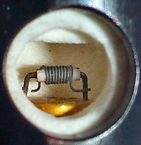
Below left: damaged IR element and initial quick fix Below right: eBay 23 turn 7R1 IR element


New text box
µ Ω ± ° ⌠ ⌡ ∫ │ ─ √ φ θ Θ ∂ δ ζ ξ ς λ ψ ω τ µ Ω ∆ Δ ∑ ∏ π Ξ ○ ≠ ³ ² ±
10⁻¹ 10⁻² 10⁻³ 10⁻⁴ 10⁻⁵ 10⁻⁶ 10⁻⁷ 10⁻⁸ 10⁻⁹