2. High Speed Current Probe
A long while back I acquired a Tek P6042 dc to 50MHz current probe http://w140.com/tekwiki/wiki/P6042 at a knock-down price. It works well (apart from a tendency for the trace [but not the measured value] to drift all the time), and has a risetime of 20ns and handles up to 10 amps peak:
https://www.edn.com/teardown-the-tektronix-p6042-current-probe-is-a-classic
When the time came to measure the dynamic ionisation switching current of the Kigre MK367 Nd:YAG flash lamp to confirm its critical damping alpha, I needed something capable of much higher current and was lucky to find a Pearson 410 solid core current monitor http://pearsonelectronics.com/pdf/410.pdf on eBay UK for just £88.
The 410 is capable of 50A dc and up to 5kA peak but like the 50MHz P6042, its rise time is 20ns. More then adequate for a slow flash lamp, but less accurate for measuring a DIY nanosecond-switched Pockels cell driver when ringing would be introduced to the rising edge (see Pearson App Note under RISE TIME).
I also found not all current probes that measure ac current are designed to measure current pulses and some that claim to be for EMC analysis also do not. Most current probes are designed to measure continuous ac (CW) waveforms only (TEKBOX TBCP1-200 RF Current Monitoring Probe, email: The TBCP1/2/3/4 series are RF current monitoring probes for EMC applications, bred for HF and high sensitivity, not current pulses, therefore no rise time is specified. However the TBPCP series is intended for current pulse measurement: https://www.tekbox.com/rf_probes/#RFPulseCurrentMonitoringProbes
Pearson's current monitor series can measure both, and their website provides a selection of links to design tips, some of which are reproduced below.
https://pearsonelectronics.com/
For my Pockels cell application, I am only interested in measuring current pulses and transients.
CURRENT PROBES FOR PULSE MEASUREMENT
PEARSON: HOW TO SELECT A CURRENT MONITOR (abridged - see website for full version)
https://pearsonelectronics.com/support/application-notes/how-to-select-a-current-monitor
'These monitors are able to measure pulses, transients and continuous signals...but not dc current...
Pulse Signals
1. For a single pulse, estimate the maximum peak current (amps) and the maximum pulse length (seconds).
Multiply these together to obtain the current-time product (amp-seconds). Choose a model with adequate peak current and current-time product to cover the requirement of the pulse to be viewed.
2. For repetitive pulses, consult the app Notes and be sure that average dc level (zero frequency component) does not exceed specifications.
3. The rise time of the pulse to be viewed should be longer than the rating of the current monitor to avoid excessive overshoot and ringing.
4. For a rectangular pulse the deviation from a perfectly flat top is given by the droop rate. Multiplying the pulse length by the droop rate will yield the percentage deviation from the flat-top value at the end of the pulse.'
CURRENT PROBE SPECIFICATIONS
https://pearsonelectronics.com/support/application-notes/specifications
'For pulse applications the time domain parameters are:
Maximum Peak Current - This value is based primarily on the voltage-breakdown rating of the connector used. For instance, a 500V rating on the connector gives a 5kA peak current rating for a 0.1 volt-per-ampere current monitor.
Droop - The value listed is the maximum amount to be expected at current levels above a few amperes. At low current levels, low initial core permeability may cause higher droop values and a corresponding increase in the low-frequency -3dB point for some models. Droop occurs when the signal is at a dc level as the transformer cannot pass dc.
Usable Rise time - If the 10 to 90 percent rise time is greater than the specified usable rise time, initial overshoot and ringing will be less than 10% of the pulse step amplitude.
I/t Max - This parameter is analogous to the voltage-time constant of a pulse transformer. The product of current times time for a rectangular pulse must not exceed the value listed or the core will saturate, causing a distorted waveform. If two turns are used through the window to obtain twice as much sensitivity, the I/t rating necessarily will be halved.'
TRANSIENT LIMITATION
This design note warns not to exceed the probe's energy rating:
https://pearsonelectronics.com/support/application-notes/transient-limitation
'When monitoring high current transients it is possible to exceed the internal dissipation limits of the unit. For unidirectional currents saturation of the core protects the secondary circuit. The energy of a bidirectional transient is not limited in this way. The heat generated by such a transient current is proportional to the time integral of the square of the current. For any given model the limit can be found by multiplying the peak current rating by the I x t product. Exceeding this I²t value may damage the unit. For example, the I²t limit for the 301X would be 50kA times 22A-sec, or 1.1 x 10^6 A²-sec. If an ac current of 5kA RMS were applied, max duration should be 1.1 x 10^6/(5 x 10³)² = 4.4 x 10^-2 sec.'
RISE TIME
A probe with a slower rise time than the signal will introduce ringing into the displayed waveform:
https://pearsonelectronics.com/support/application-notes/rise-time
https://pearsonelectronics.com/pdf/Rise%20Time.pdf
This note illustrates the difference between using a Pearson 110 (20ns) and a Pearson 2877 (2ns) to view a 12.9ns signal risetime. Phantom ringing is clearly evident with the slower probe. My 20ns Pearson 410 would introduce the same ringing for this signal.
PEARSON RANGE
A comparison of Pearson's fixed core monitor range is here:
https://pearsonelectronics.com/products/wideband-current-monitors
A comparison of Pearson's clamp-on monitor range is here:
https://pearsonelectronics.com/products/clamp-on-current-monitors
My Pearson 410 [E3] is rated 20ns 5kApk and was £88 on eBay UK in 2011. At the time I didn't know this was an incredible bargain even for eBay. An ideal probe would be the Pearson 2877 2ns 100Apk 200MHz, listed $335 refurbished (another low price) at AccuSource Electronics, but out of stock:
https://accusrc.com/product-Pearson-2877-7367
Pearson 410 (20ns) Pearson 2877 (2ns)
https://pearsonelectronics.com/pdf/410.pdf https://pearsonelectronics.com/pdf/2877.pdf


Given the prohibitive cost of new ones, I wondered if I could make my own fast current pulse probe.
Below is a link to the 4HV high voltage projects forum where member Mads Barnkob posted a
partial teardown of a damaged Pearson 1330 (250ns) https://pearsonelectronics.com/pdf/1330.pdf
Pearson current monitor model 1330 teardown (100kA):
https://4hv.org/e107_plugins/forum/forum_viewtopic.php?175696
This teardown reveals there is far more to the design than a ferrite core and a simple winding. The author sums up his photographs of the embedded wires and resistors with a schematic sketch at the bottom that implies a distributed LCR / π network is present. He reveals a potted 39Ω series resistor contributes to Pearson's expected dc resistance of 46Ω (Pearson: 'The 1330 should measure ~46Ω. If it is much higher this usually indicates a damaged series resistor which can affect the sensitivity when using a 50Ω load.'), a good reason why it is wise not to exceed the manufacturer's Transient Limitation (above).
Further down this page another poster Finn Hammer adds teardown photos of a Pearson 110 (20ns):
https://pearsonelectronics.com/pdf/110.pdf
Below left, 1330 teardown Below centre, 1330 schematic guess Below right, 110 teardown
602j03x 602j04x 602j05x
A potential alternative to a Pearson current monitor is a DIY i-dot sensor, synonymous with the v-dot sensor in [Research: High Speed kV Probe].
PPM Test manufactures i-dot sensors.
The difference between a current probe and an I-dot sensor
https://ppmtest.com/current-probe-v-i-dot-sensor
The following is reproduced from the above website (PPM - Pulse power & Measurement Ltd):
Current probe
'A current probe is not really a current sensor, because it does not respond to direct current. A current probe is designed to sense and integrate the first derivative of the current, or more precisely, the magnetic field associated with the current being measured. A current probe is a self-integrating I-dot sensor.
A current probe is a current transformer: the measured current flows in a one-turn primary -winding- and the signal current flows in the N-turn secondary winding. The sensitivity (transfer impedance Zt) of a current probe depends on the number of turns (N) in the secondary winding and the load impedance of the secondary winding, usually a 50Ω cable, which may be combined in parallel with an internal resistor to adjust the transfer impedance.
The performance of a current probe is limited by standoff voltage at critical points in the probe, such as the connector or the internal shunt resistor, induction saturation in the core and resistive heating in the winding. Standoff voltage limits the output voltage to 2000V in probes without an internal resistor and to 400V in probes with an internal resistor. Induction saturation limits the measured current and the time interval during which it can be applied.
The output of a current probe
Vout = Zt x Isensed
where Zt = transfer impedance
I-dot sensor
In contrast, an I-dot sensor can correctly be called a current sensor, because it is designed to sense the first derivative of the magnetic field associated with the current being measured. In other words, the output is proportional to the time rate of change of the aperture current.
The output voltage from an I-dot sensor is a linear function of the frequency of the current being sensed, whereas the output voltage from a current probe is independent of frequency in its useful bandwidth. In fact, the useful bandwidth is defined as the frequency range for which the output voltage is independent of frequency - the theoretical lower limit being the transition frequency.
The sensitivity of an I-dot sensor is determined entirely by its physical dimensions. It does not need to be calibrated, because the dimensions do not change over time. I-dot sensors are available with sensitivities ranging from 0.5nH to 10nH as standard, and a much wider range is possible if required. Risetimes for these sensors range from 0.17nH to 1.8nH [I pointed this typo out to them but was ignored]
which corresponds to upper 3dB frequencies from 190MHz to 2GHz. The wide range of output voltages (5mV to 5kV) and the differentiating mode of these sensors enable them to meet a wide variety of measurement requirements.
The output of an I-dot
Vout = M dIdt
where M = sensor mutual inductance (H), I = total current through aperture (A)
I-dot sensor versus current probe:
I-dot sensor Advantages
Needs no periodic calibration
Wider operating bandwidth
Larger max output = greater dynamic range
I-dot sensor Disadvantages
Output must be integrated to calculate current
Current probe Advantages
Provides a pre-integrated signal
Current probe Disadvantages
Narrower bandwidth
Inductive and thermal limitations
Requires periodic calibration'
https://ppmtest.com/current-probe-v-i-dot-sensor
There is a parameter list for of all of their Prodyn current probes near bottom of the page.
(this list isn't on their current probes page)
https://ppmtest.com/product-category/current-probes
The left of this page has links to all of the others listed below:
Current Probes / Current Clamps
Passive Integrators
Magnetic field (B-DOT) sensors
Electric Field (D-DOT) Sensors
CURRENT PROBES FOR ac MEASUREMENT
PEARSON: HOW TO SELECT A CURRENT MONITOR (abridged - see website for full version)
https://pearsonelectronics.com/support/application-notes/how-to-select-a-current-monitor
Continuous Signals
1. Determine the approximate maximum sine-wave amplitude, I (amps), and the approximate minimum frequency, f (Hz).
2. Compute I/f (amps/Hz). To use a given model, this should not exceed the spec sheet value.
3. Compute the maximum RMS current. To use a given model, this should not exceed the spec sheet value.
4. Determine if the frequency over which the monitor is to be used is within the range of the low and high 3dB points. The monitor will lose its accuracy outside of this range.
PEARSON SPECIFICATIONS
https://pearsonelectronics.com/support/application-notes/specifications
'For the continuous signal applications, the frequency domain parameters are:
Maximum RMS Current - This value is based on heating considerations involving the long-term stability of the internal resistance element in the current monitor.
Approximate Low And High Frequency 3 dB Points - Due to the ac nature of transformers, the flat midband response will roll off at low frequency. The “corner” or “cut-off” frequency, at which the response is 3 dB down, is specified. Internal resonances determine the useful high frequency cut-off point. Response is within ± 3 dB at the specified high frequency limit.
I/f Max - This parameter is to sine-wave currents what the I•t product is to rectangular-wave currents.
The quotient of peak current divided by frequency must not exceed the listed value or the core will saturate. If two turns are used through the window to obtain twice as much sensitivity, the I/f rating necessarily will be halved.'
Current probes generally used for ac measurements
Note, some of these may also measure current pulses. Consult manufacturers' datasheets. The relationship between bandwidth and rise time loosely follows this equation:
[Q1a] BANDWIDTH wrt RISE TIME
Bandwidth (Hz) = 0.35 Example: Bandwidth 200MHz = 0.35
Rise time (s) 1.75ns
[Q1b] RISE TIME wrt BANDWIDTH
Rise time (s) = 0.35 Example: Rise time 4ns = 0.35
Bandwidth (Hz) 87.5MHz
A variant of this equation is presented on page 42 of ETS-Lindgren's 90k series current probes brochure, with the constant 0.35 reduced to 0.30: https://docplayer.net/369552-Current-probes-user-manual.html
However none of the individual datasheets in this brochure specifies risetime, suggesting none of the listed probes is intended for pulse measurement.
Historically, the 90k series has been manufactured by a large number of companies including Ailtech, Eaton, Singer, Solar, Stoddart and Tagem, if not more.
Of significant interest for ac measurement, is the logarithmic impedance curve depicted for each model as this determines the correlation between actual and measured current over frequency. Pearson provides a small number here: https://www.pearsonelectronics.com/applications/emi-testing-applications
The following curves are for the Fischer F-65 and generic 94111-1/2 probes mentioned below:
![602j06x F-65 current probe transfer impedance curve [E59].jpg](https://static.wixstatic.com/media/d58027_f633eb86c0804764aaf88563de76217f~mv2.jpg/v1/fill/w_337,h_214,al_c,q_80,usm_0.66_1.00_0.01,enc_avif,quality_auto/602j06x%20%20F-65%20current%20probe%20transfer%20impedance%20curve%20%5BE59%5D.jpg)
![602j07x 94111-1 current probe transfer impedance curve [E57 P.53].jpg](https://static.wixstatic.com/media/d58027_53d27757a53f48b99b8071cfb8d55dc5~mv2.jpg/v1/fill/w_285,h_233,al_c,q_80,usm_0.66_1.00_0.01,enc_avif,quality_auto/602j07x%20%2094111-1%20current%20probe%20transfer%20impedance%20curve%20%5BE57%20P_53%5D.jpg)

HIGH SPEED COMMERCIAL CURRENT PROBES
High speed current probes capable of accepting kV are simpler than kV voltage probes, but new ones are very expensive, although they have the advantage of being supplied with measured transfer impedance calibration data, unfortunately always lost by the time they appear on eBay. I identified the following manufacturers (there are probably many more). Probes come in both fixed and open clamp type designs, the latter being easier to use but more expensive and usually inferior to solid cores but as with most things, convenience is usually a compromise. Below, clamp types from alternative manufacturers:
Tegam (also Eaton, Singer)
clamp-on 94111-1 1MHz-1GHz 50Apk N-type. For a datasheet, see pages 22,23,33,53 of following manual:
[E57]: ETS-Lindgren Current Probes User Manual,
https://docplayer.net/369552-Current-probes-user-manual.html
The 94111-1 isn't a conventional current monitor; it is designed to measure radiated current, not conducted current. Rise time isn't explicitly declared for the 94111-1 but when I asked ETS-Lindgren they said it should be around 300ps. Its non-horizontal progressive transfer curve (see above, centre) is due to it having no inherent load resistance, making it also suitable as a current injection probe. However it is usable for either application.
The conventional 94111-2 conducted current variant has a flatter curve. They usually go for $$$ and the pristine one above was a bargain at $400 but a US buyer beat me to it whilst I was requesting UK shipping as eBay wouldn't let me buy it without this being declared. Later I bought an old and tatty Singer 94111-1 for $250, but found it was faulty.
http://www.ets-lindgren.com/products/probes-monitors/emc-probes/current-probes/9006/900609
Nelow, the Tagem 94111-1 current probe:


Below, the Fischer F-33-2 current probe:


Fischer Custom Communications - Fastest in 2020 is 4GHz
https://www.fischercc.com/type/current-monitor-probes/
Fischer (FCC) F-65 RF Current Monitoring Probe, 100kHz-1GHz 100Apk N-type, data sheet:
https://www.valuetronics.com/pub/media/vti/datasheets/Fischer%20Custom%20Communications%20F-65.pdf
Also called current injection probe. 'The clamp-on F-65 is capable of measuring pulse transients with risetimes of 200ps and a pulse width of 35ns. This probe has a small outer diameter, approximately 71mm with an internal diameter of 32mm. Its transfer impedance is 1Ω from 1MHz to 1GHz. It can operate up to 350A dc to 400Hz, 3A CW and 100A peak pulse current.'
12/01/20 There was a 1kHz-250MHz Fischer F-33-2 on eBay for $50
https://www.theemcshop.com/current-monitorsensing-probes/998-fischer-fcc-f-65-rf-current-monitoring-probe-10-khz-1-ghz.html
OTHER MANUFACTURERS
Ion Physics
Ionphysics in 2020 fastest is 3ns:
https://ionphysics.com/ac-and-pulse-application-monitors
Stangenes in 2020 fastest is 10ns:
https://electricalproducts.stangenes.com/viewitems/current-transformers/pulse-current-transformers
Solar Electronics fastest is 9142-1N 500MHz, Tr not specified so unlikely to be for pulses.
https://www.solar-emc.com/RFI-EMI.html
https://www.solar-emc.com/RFI-EMI.html#specs
Others:
Eaton 94606-1 = 10kHz to 100MHz / 94606-2 = ? to 70MHz / 94606-4 = ? / 94606-6 = 5kHz to 5MHz
Historical: Stoddart, Ailtech, Solar, Singer, Genistron (later Genisco),
examples: Genistron GCP 5120 is 30Hz to 15MHz, Genisco GCP-5130 is 15kHz-50MHz 300A
List of current probes and their manufacturers (but no links to them):
https://wiki.dare.nl/wiki/index.php/Category:Current_Sensor
Korean company Tekbox offers low cost unhinged current probes, starting in 2020 with the $299 TBCP1-200 rated up to 80A (RF 3A) covering 10kHz to 500MHz; 200MHz to -3dB, but it only works with CW signals:
ttps://www.tekbox.com/product/tbcp-rf-current-monitoring-probe, UK distributor Telonic:
https://www.telonic.co.uk/TEKBOX-TBCP1-200-RF-Current-Monitoring-Probe-p/tbcp1-200.htm
In 2019 EDN magazine carried out a review of Tekbox's earlier 200MHz model and found it compared favourably against the significantly more expensive hinged Fischer F-33-1:
https://www.edn.com/review-tekbox-tbcp1-rf-current-probe
More models have since been launched.
CVRs
An alternative to ferrite core-based current probes is the Current Viewing Resistor, which as its name suggests is essentially a resistive element placed in the current path. Despite the relative simplicity, CVRs also often sell for $1000s. CVRs are ideal for current pulse measurements.
US-based T & M Research: https://www.tandmresearch.com/index.php?page=products
CVR terms explained: https://www.tandmresearch.com/index.php?page=cvr-info
This paper from T & M compares design trade-offs & equations and bandwidth plots of theoretical CVRs:
http://www.ib-billmann.de/bilder/pdf/05_CVRAnalysys-Rev7.pdf
T & M CVRs are typically tubular or slab shaped. There are many different models: 250kHz to 2GHz,
rise times from 2µs to 180pS, pulse energies 1J to 82kJ (W 12.5s), and power 2W to 275W (R-series):
http://www.ib-billmann.de/bilder/pdf/140515_IB_M.Billmann_Koax-Shunt.pdf
Some 2022 prices: https://www.interworldna.com/PriceLists/pricelist_main.php?catName=TandM&ct=1
DIY CURRENT PROBES
Here is a novel approach that turns a resistive potential divider into a current probe:
'Construct a resistive potential divider that say operates to reduce the input voltage by 1000 to 1. You'll need several resistors to do this of probable value greater than 1MΩ and they'll need to have a voltage rating that is suitable. If you do consider using several series resistors to build up the potential divider, take extra care with this because any significant capacitance difference between one resistor and the next can cause problems with resistors dying - the one with the least effective parallel capacitance "receives" the transient when applying the high-voltage. This can cause it to breakdown and suddenly the whole bunch can go "pop".
Try to stick with a single high-voltage resistor or preferably a self-contained potential divider like those from Vishay. My answer is basically the same, except that you use an I/V converter at the low side. You treat the high resistance with a high voltage across it as a current source. You convert that current to a voltage. The advantage is that the output of the high resistance is a virtual ground, so you can protect it easily with two anti-parallel diodes.'
Having already visited the HV probe scene and discarded it in favour of the much simpler D-Dot, I dismissed this idea too, but it is an interesting variant.
DIY CURRENT MONITORS FOR RF EMC WORK
'Simple RF Current Transformer for EMC/EMI Investigation', by James Pawson at Unit 3 Compliance Ltd UK:
https://www.unit3compliance.co.uk/simple-rf-current-transformer-emi-emc-investigation
Two links in it: links and useful lead to the following excellent articles:
links '6.2 Current Transformers: Part 1' by D.Knight (G3YNH) with circuits and all the maths:
http://g3ynh.info/zdocs/bridges/Xformers/part_1.html
useful 'The HF Current Probe: Theory & Application', in the EMC Directory & Design Guide dated 2012,
by Kenneth Wyatt at Wyatt Technical Services, USA, on how to build a DIY current probe:
http://www.interferencetechnology.com/wp-content/uploads/2012/04/Wyatt_NA_DDG12.pdf
Kenneth describes two designs; one using a standard ferrite toroid and a second using a split core clamp-on ferrite choke from Steward [D34] - Now Laird Technologies, which appeals more:
https://uk.farnell.com/laird-technologies/28a3851-0a2/ferrite-core-13mm-100mhz-260r/dp/2292251
a) ROUND ferrite split core part 28A3851-0A2 FEC #2292251 PRICE £5.99 on 14/01/20
Z @ 500MHz = 600Ω
Z @ 300MHz = 410Ω = 10Ω less difference than square one.
Z @ 100MHz = 260Ω (MIN 224Ω)
Z @ 10MHz = 93Ω
Z @ 1MHz = 12Ω
https://uk.farnell.com/laird-technologies/28a2024-0a2/ferrite-core-13mm-100mhz-280r/dp/2292239
b) SQUARE ferrite split core part 28A2024-0A2 FEC #2292239 PRICE £3.92 on 14/01/20
Z @ 500MHz = 600Ω
Z @ 300MHz = 440Ω
Z @ 100MHz = 280Ω (MIN 208Ω)
Z @ 10MHz = 93Ω
Z @ 1MHz = 12Ω
Kenneth says their type 28 material is useful from 10MHz to 1GHz but the FEC datasheet performance curves shows them only going to 500MHz.
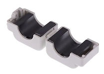
However at the top of James Pawson's article, his obscure link £5 from RS is to a 1GHz split-core ferrite from Würth Electronik's Star-TEC series, core material: NiZn (4W620), MAX CABLE DIA 16mm
https://uk.rs-online.com/web/p/ferrite-sleeves/7568386
c) SQUARE ferrite split core part #7427154 [D35] RS #756-8386 PRICE £6.49
Below is a comparison of ac current measurement using this DIY probe vs Pearson and Tek P6042:
https://www.youtube.com/watch?v=UAA9oqHGUqA
Z @ 1GHz = 600Ω
Z @ 300MHz = 220Ω
Z @ 100MHz = 130Ω
Z @ 25MHz = 71Ω
Z @ 10MHz = 45Ω
Z @ 1MHz = 6Ω
Dimensions (outside plastic):
20mm long x 35mm wide x 32mm closed
1.27" x 1.38" x 1.26" Above: Pearson 5664


DIY CORE TBD
This last core may be the one in the photo at the top of James Pawson's article and is the closest mechanically to the commercial probes, although much smaller (not a bad thing), and is the idea I shall experiment with first.
There is a warning this probe design will likely work no faster than ~200MHz, but I saw no harm in having a go particularly as transients are of greater interest that absolute bandwidth, and it should keep me occupied until the next bargain comes up on eBay, because I have no doubt I will eventually require a professional solution.
Kenneth wound 7 turns of teflon-insulated wire wound around one half, glued down on the inside to hold the windings side by side. He chose teflon coated wire to counter chaffing; I have a reel of PTFE wire which is the same thing. He epoxied a pcb board style BNC to the outside, also holding the outside turns in place.
The number of turns is significant beyond just matching current: 'More turns increase the self-capacitance and self-inductance.'[affecting speed] https://en.wikipedia.org/wiki/Current_sensing
I could remove the plastic around the ferrite and make my own custom hinged enclosure for it from copper clad pcb, which would be much easier to work than metal, and form a good EMC seal to an SMA or BNC connector. This assumes the metal outside cover is there for mechanical strength rather than assisting the magnetic field (many look like cast aluminium; Prodyn's resemble steel plate). Alternatively I could try a hingeless design like the Pearson 5664 (above). My old reel of Chomerics EMC tape can cover the core interior and any copper breaches, and hold the secondary PTFE wires in place. There is also the possibility of adding David Jewsbury's Poor Man's DIY 1GHz Active Probe [E46]
within the enclosure, although it will require a 5V power supply.
Kenneth explains how to use a spectrum analyser or network analyser to qualify the probe, and I can use my Signal Hound TG and SA for this.
OTHER RESOURCES
A similar DIY guide using a Würth Elektronik 74271251 split core:
https://clearemc.com/building-a-current-probe-emc
Some while after discovering the above, I came across these excellent articles from EDN. The first covers voltage probes and the second differential voltage probes and current probes.
Both include detailed calculations and recommended construction techniques:
https://www.edn.com/build-your-own-oscilloscope-probes-for-power-measurements-part-1
https://www.edn.com/build-your-own-oscilloscope-probes-for-power-measurements-part-2
New text box
µ Ω ± ° ⌠ ⌡ ∫ │ ─ √ φ θ Θ ∂ δ ζ ξ ς λ ψ ω τ µ Ω ∆ Δ ∑ ∏ π Ξ ○ ≠ ³ ² ±